SFX-100 Motion Platform – Traction Loss and Surge
Adding traction loss to the SFX-100 motion platform is one of the best upgrades to do, it really adds to the immersion and gives that extra dimension of feeling when the car starts to slip. Traction Loss is not a simple addition however, it requires an additional slip platform below the rig to allow it to move laterally in both directions, so be prepared for a lot of work. But when your finished adding traction loss your rig, it will look much bigger and cooler than before!
Contents
Bill of Materials
1. 3d printed STL files:
- The modified 3d printed parts are listed in the section below.
- Standard Actuator Parts
- Bump Stop
- Linear Bearing Mount
- Motor Mount
- Foot Cap
2. Push-Pull Actuator
- Modified Hollow bar with threaded ends per image below. Source: NTL Bearing – Amy <skye@ntl-bearing.com>.
- 2 No M5 x 90 socket head bolts. Source: https://www.accu.co.uk/en/cap-head-screws/2860-SSC-M5-90-A2
- M30 Thin Fine Pitch Hexagon Nut 1.5mm pitch. (Note: I used a stainless nut but this was difficult to tap the thread, I would recommend to source a mild steel nut or ask the supplier of the hollow bar to also supply the drilled and tapped Nut.)
- All other standard actuator contents are also required, which are not modified above.
3. Connection from Actuator to Rig
- Linear Rail – HGR20 Square Linear Rail Guide and 1 No HGH20CA Carriage. Source Aliexpress: https://www.aliexpress.com/item/1005001385827841)
- M12 Rose Joint. Source: NTL Bearing – Amy <skye@ntl-bearing.com>
- 1 No M8 x 40 bolt and 1 No M8 Nylon Lock Nut for rose joint to slider.
- 4 No M5 x 12mm bolts to connect adapter to carriage.
- 2 No 90 degree brackets to support linear rail. Source Motedis: https://www.motedis.com/en/Bracket-40×80-I-Type-slot-8
- 8x Bracket 40 I-Type slot 8 including caps, t-nuts/bolts to actuator, screws to base to connect actuator to base.
4. Roller Platform
- 2x Profile 40x80L I-type slot 8 1350mm long and endcaps
- 2x Profile 40x40L I-type slot 8 660mm long and endcaps
- 8x Bracket 40 I-Type slot 8 including caps, t-nuts and bolts
- 4x SP45-FL Roller bearings
- 4x 3d printed spacers for roller bearings
- 4x Actuator Feet/Cup supports
5. Roller Platform Base
- 18mm Plywood sheet 1530mm x 940mm. I cut into 3 sections 600mm x 940mm front, 500mm x 940mm rear and 430mm x 940mm centre.
- 4 x 400mm x 210mm x 2mm Think stainless steel plates (below roller bearings). Additional length is provided for surge.
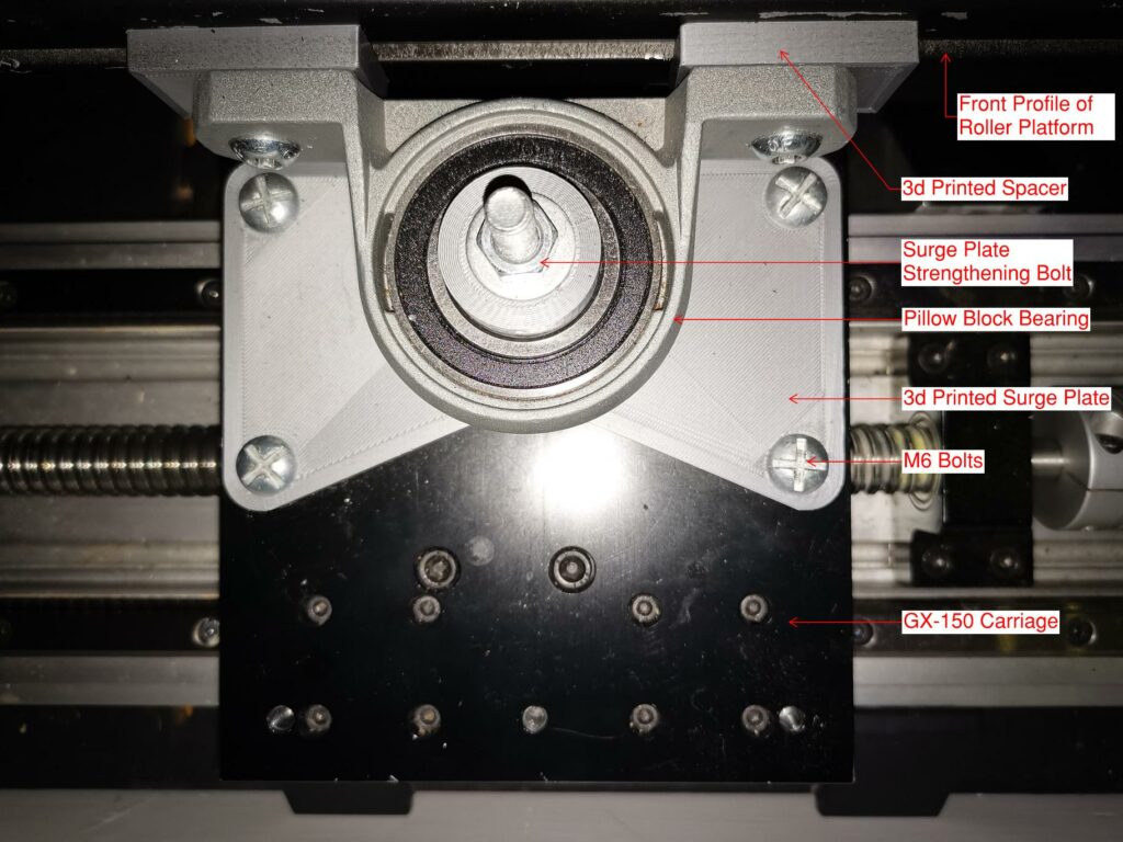
6. Front Traction Loss or Surge
- GX150 SFU2005-300mm Linear Guide Rail. Source Aliexpress: https://www.aliexpress.com/item/4001018200594
- 30mm pillow block – KP006. Source: NTL Bearing – Amy <skye@ntl-bearing.com>
- 3d printed Surge Plate.
- 4 bolts for connecting surge plate to GX150. Button Head M6 x 20mm.
- 1 bolt, washer and nut for surge plate strengthening. Countersunk M8 x 70mm.
- 2 bolts connecting pillow block to roller platform. M8x30mm*, *length depends on spacers used.
- 8mm 3d printed spacer between pillow block and roller platform.
- 8x Bracket 40 I-Type slot 8 including caps, t-nuts and bolts to connect GX150 to base.
3D Printing
The 3d printed components include:
- Modified Slider (Push/Pull)
- Modified Fixed Bearing Mount.
- Reducer for M20 hollow bar thread to M12 rose joint.
- Carriage Mount for rose joint to linear rail slider.
- Roller Bearing Spacer/Support
- Surge Plate
- Surge Plate Spacer
- M12 Rose Joint Bushing


Push-Pull Actuator
The standard actuator is a push actuator meaning that it pushes the hollow shaft down and relies on gravity to push the hollow bar back into the slider when returning. There is not a fixed connection between the slider and the hollow bar.
To use the actuator for traction loss, the actuator will be on its side so it must work when pushing and pulling the hollow bar, modifications are needed to the standard actuator to make it a push-pull actuator.
The first modification is to the slider inside the aluminium extrusion. to make it work in pull/tension, the slider and hollow bar has been threaded to allow it to be screwed into the slider instead of push fit. Along with the threaded connection, a M30 nut with two M5x90 bolts connect from one side of the slider to the other which create a clamped connection across the slider, while not increasing the slider overall length (which would reduce usable slider movement).
The internals of the slider are shown below (without the slider) to show how it works.
The second modification is to the hollow bar. Both sides of the hollow bar are threaded, one internally to connect to the slider and one externally to connect to the rose joint fixing.
")
")

The third modification is to the fixed end bearing support. The standard support relies on threaded screws into the 3d printed part. To make this more robust for tension loads (pull action) these holes have been extended through the 3d printed part and a nut placed on the top side to give additional capacity in tension.
Roller Platform
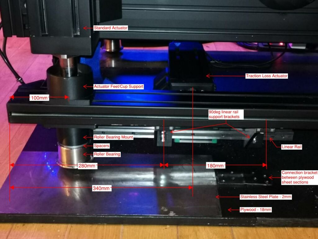
Assemble the aluminium profile as shown below, loosely add the actuator support feet to the top until they are aligned and add the roller bearing mounts and roller bearings to the bottom. The roller bearing mounts are fixed below the actuator locations to transfer the load directly down to the base.
Check that the roller platform clears the motor of the actuator because the actuator motor will be located below the side profile. If it does not provide enough clearance add a spacer between the roller bearing and the mount. I added 2 spacers to my rear mounts. The spacers are included in the 3d print files.
Add the two 90 degree brackets to support linear rail to the rear right side of the platform. These are located 280mm from the back of rig to centreline of first bracket, and are spaced at 180mm centre to centre (see photo). When installing, slide the rig forward so the carriage is beside the rear most bracket, tighten this bracket then slide the rig back so the carriage lines up with the front bracket. Then tighten this bracket. This ensures that the linear rail is lined up with the slope of the rig.


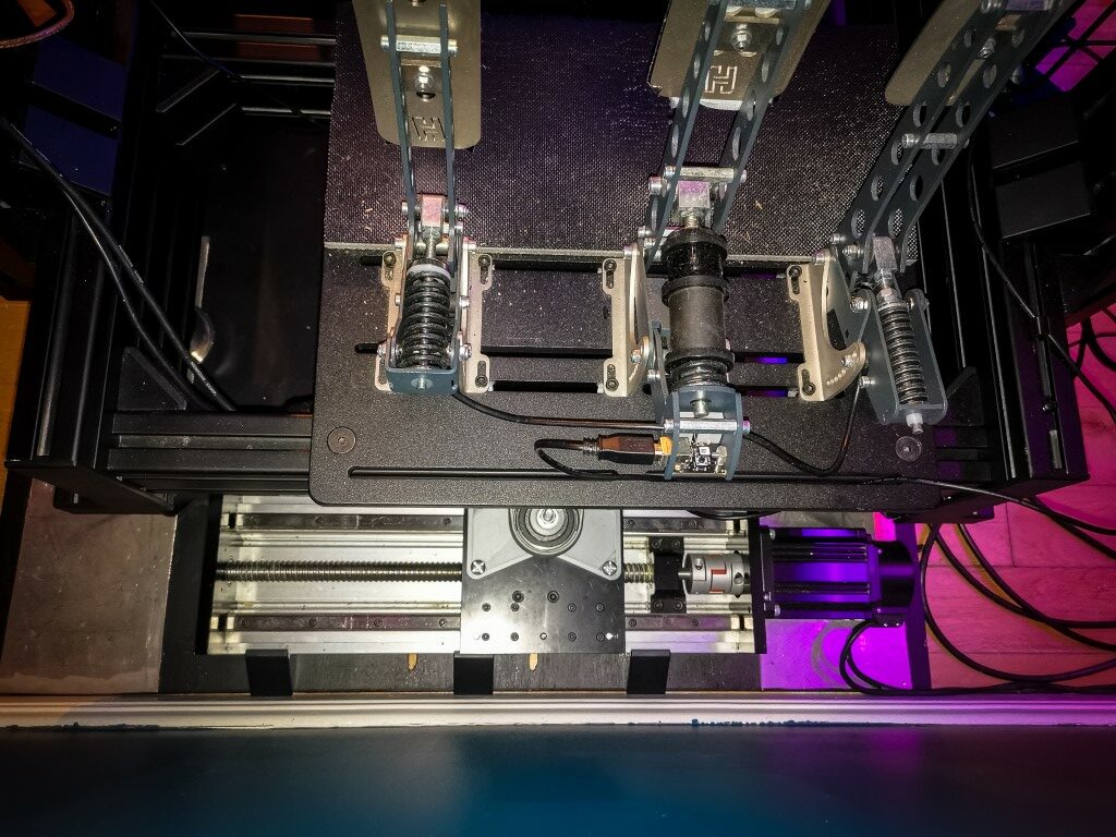
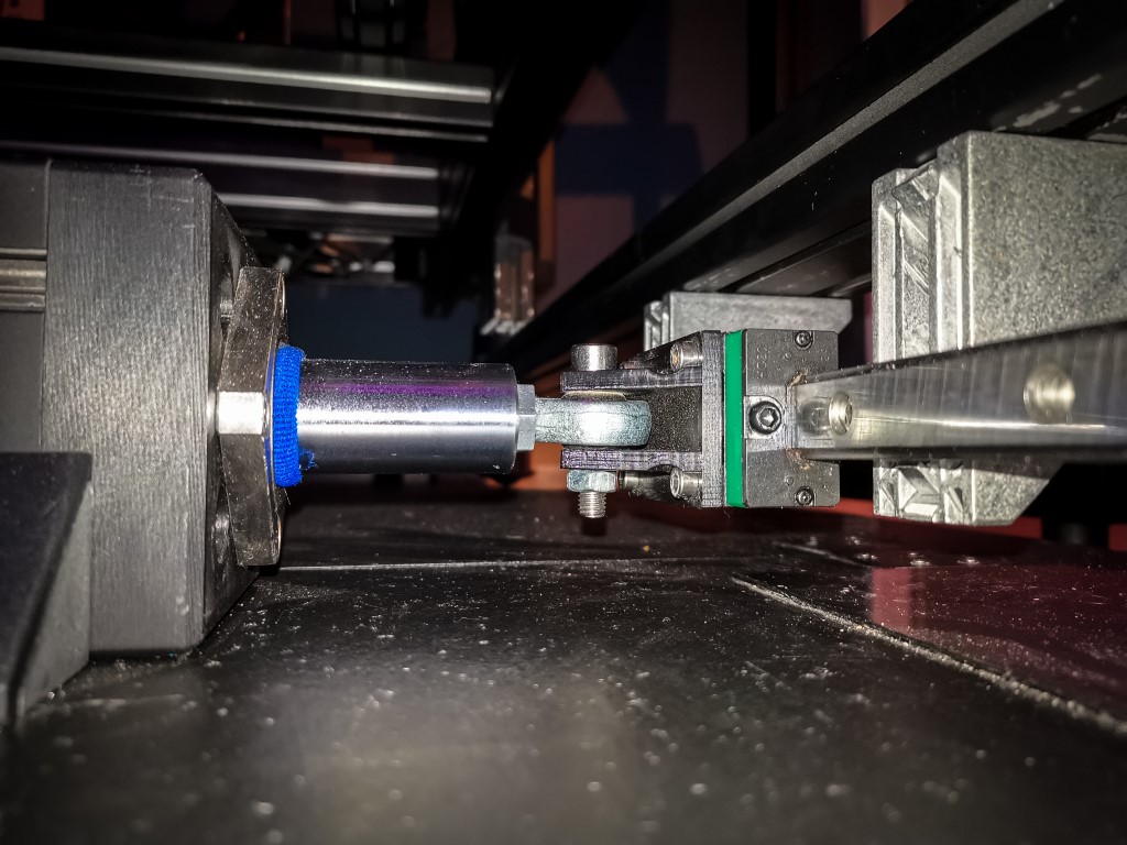
Connecting Actuator to the Roller Platform
The actuator to roller platform is shown in the photos below. The rose joint is connected with a 3d printed adapter and the other side of the rose joint is connected to the 3d printed carriage adapted. There is a bushing inside the rose joint connection to remove any play in the M8 bolt connection which is not visible on the photos.

")

Roller Platform Base
The roller platform base is made from a sheet of 18mm plywood cut to 1530mm x 940mm and painted black. The traction loss actuator is screwed into this base at the back of the rig, and the surge linear rail guide is screwed into the base at the front of the rig. I used to use surge and traction loss, but converted the surge effect to front traction loss by rotating 90 degrees.
The four stainless steel plates are placed in the corners of the plywood sheet and glued down with contact adhesive. The stainless steel plate sizes allows for traction loss and surge to be used.
Servo Parameters – Rear Traction Loss
There are no changes to the servo parameters for the rear traction loss. These are the same as the base SFX-100 settings.
Profile Settings
The image below shows the Rear Traction Loss profile settings. Follow the steps below to set it up:
- Create a new profile for 2 Traction Loss. ( I add a “2” prefix for all controller 2 motors)
- Assign the controller ID to 2. (The controller ID 1 will be your main SFX-100 controller.)
- Assign the motor for the traction loss into Type. My motor is motor 4.
- Assign the telemetry key to SlipAngle for TL Slip.
- I have used a min/max position of +-100, this controls how much (distance) the actuator will move.
- Min/Max Telem is +-10. I use this for most cars, except for rally cross where I have increased to +-30 due to the rotation of the car. This can be tuned per car based on real-time data.

Surge or Front Traction Loss – Front Connection
For traction loss the front of the rig needs to pivot about a point and allow the rear to rotate. However, we can also fix this pivot point to an additional linear guide creating a surge or front traction loss effect.
I initially deigned this for surge, but there were 2 reasons I changed to front traction loss
- When I use VR it really dislikes surge movement and makes the VR position in car jump around making it undrivable in VR.
- I could not get the surge effect dialled in to my liking. What I mean by this is that the initial braking effect was good, sending the rig backwards and giving that push forward feeling however when removing the brake it also surged the opposite way when returning back to centre, feeling like an acceleration when coming off the brake. (not good).


")
")
Servo Parameters – Front Traction Loss
There are no changes to the servo parameters for the rear tractionloss. These are the same as the base SFX-100 settings.
Profile Settings
I have set up 2 profiles for the front motor.
The first is Front Traction Loss based on slip angle. This profile complements the rear traction loss by moving in the opposite direction giving a more emphasised feeling of slip angle.
The second profile is based on Lateral acceleration. This gives a feeling that the car turns into the corner when you make the turn by moving the front of the rig in that direction. There is also a more subtle feeling of understeer when the lateral acceleration reduces due to front tyre slip, however this is subtle compared to the full lateral acceleration of the car during cornering.
The image below shows the front Traction Loss profile settings. Follow the steps below to set it up:
- Create a new profile for Front TL Slip.
- Assign the controller ID to 2. (The controller ID 1 will be your main SFX-100 controller.)
- Assign the motor for the front traction loss into Type. My motor is motor 1.
- Assign the telemetry key to SlipAngle for TL Slip.
- I have used a min/max position of +-100, this controls how much (distance) the actuator will move. I have only used +-50 in the graphed area.
- Min/Max Telem is +-10. I use this for most cars, except for rally cross where I have increased to +-30 due to the rotation of the car. This can be tuned per car based on real-time data.
- Create a new profile for Front TL Lat.
- Assign the controller ID to 2. (The controller ID 1 will be your main SFX-100 controller.)
- Assign the motor for the front traction loss into Type. My motor is motor 1.
- Assign the telemetry key to LatAccel for TL Lat.
- I have used a min/max position of +-150, this controls how much (distance) the actuator will move. I have only used +-100 in the graphed area.
- Min/Max Telem is +-5. I have only used +-4 in the graphed area. This can be tuned per car based on real-time data.
