SFX-100 Motion Platform
The SFX-100 is a DIY motion simulator platform for sim-racing. It gives the ordinary gamer an opportunity to build a motion platform for a fraction of the cost of commercially available equivalents. The official build guide for the SFX-100 is available here; https://opensfx.com/ and there are other build guides available online which will also be useful to read.
This guide will give my experience with the build process and fill in any gaps or modifications that I made across along the way. It will also show how to expand the base SFX-100 platform to include surge, traction loss, front traction loss and belt tensioner effects.
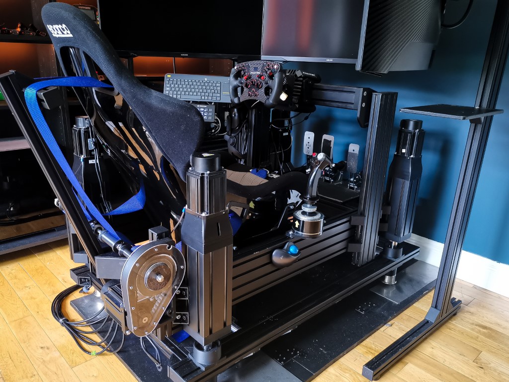
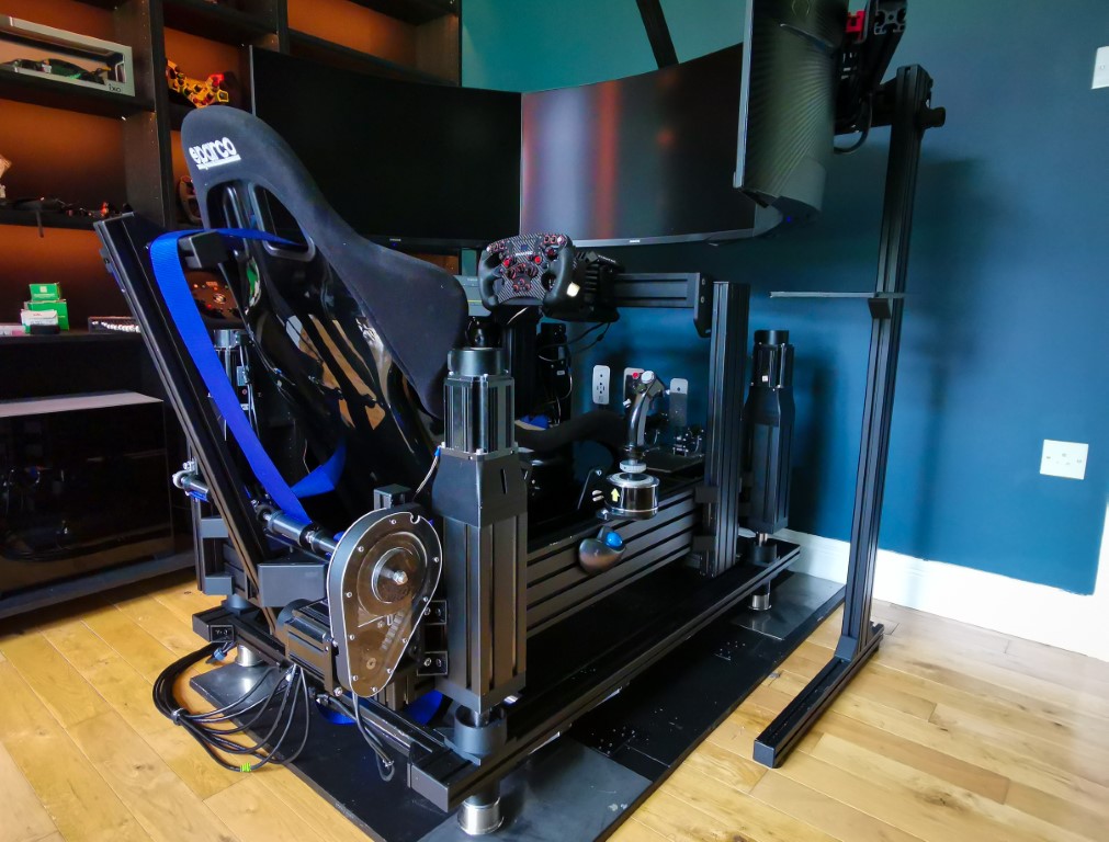
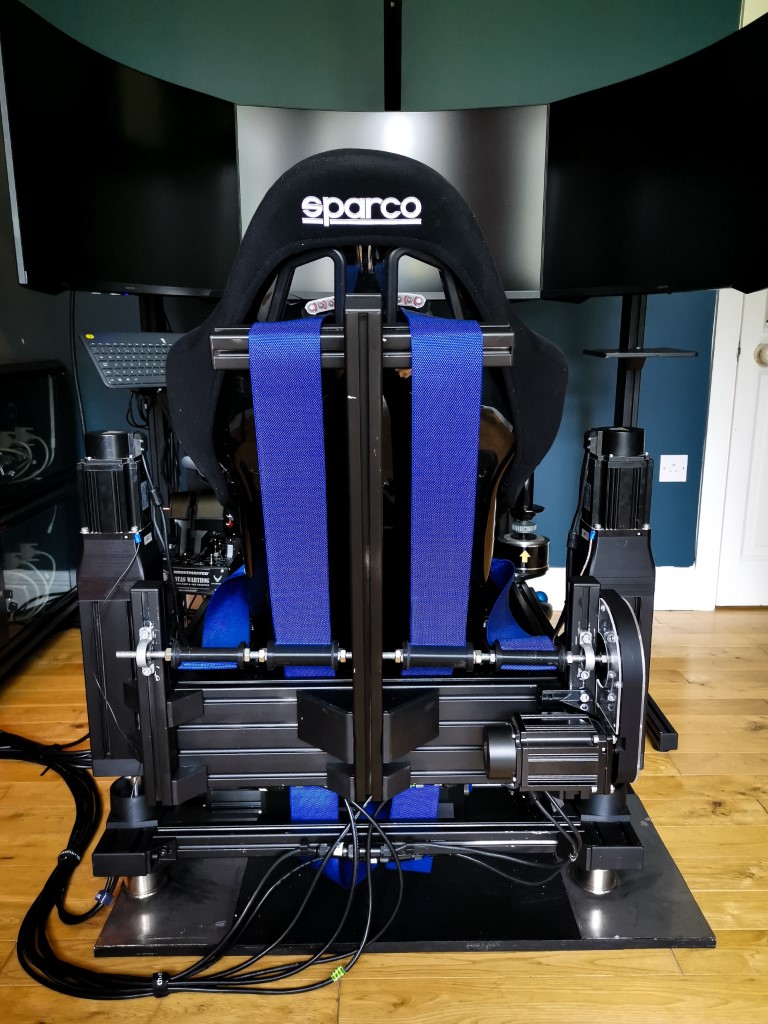
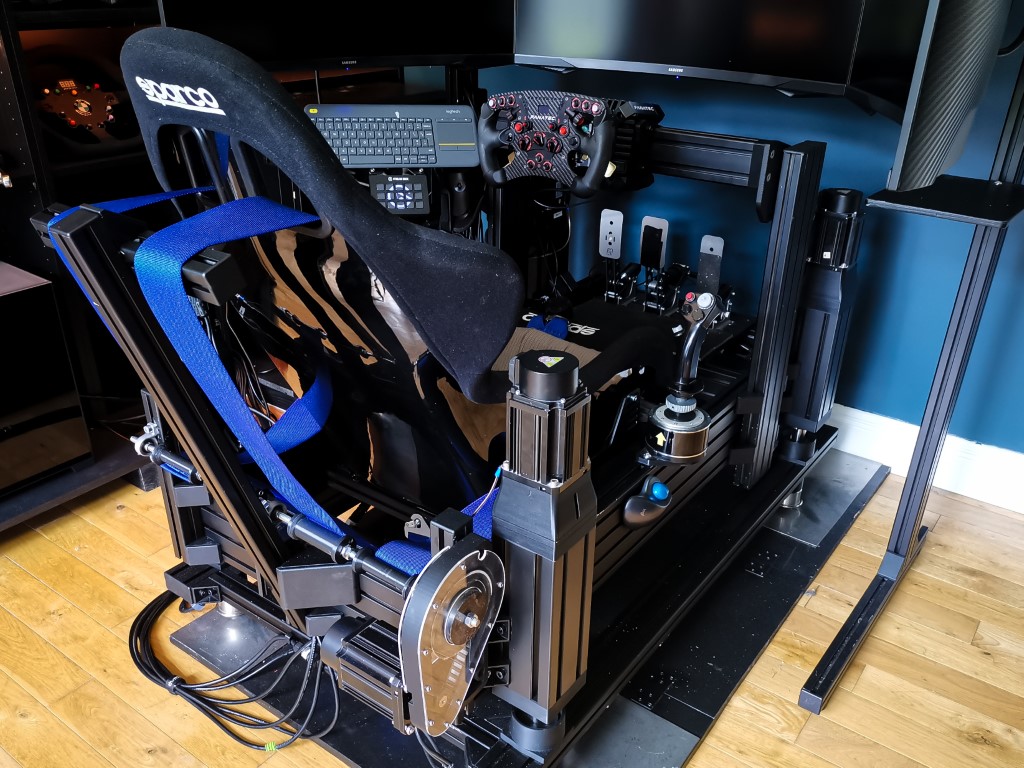
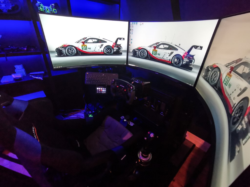
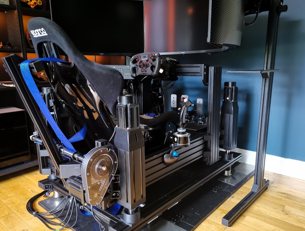
Showcase
Before we get into the details, here are are photos of the current rig, as with all things DIY its still getting updates and improvements but it has come a long way in the past 3 years. I have added traction loss, front lateral movement and a belt tensioner on top of the base SFX-100 platform.
")
")
")
")
")
")
Your Rig
Before we even start with the SFX-100, we need to discuss your current rig. It should really be an aluminium profile rig so that the actuators can be bolted to the side of it to turn it into the motion platform. This can be a purchased rig or a DIY rig but it should have a 4080 profile as a minimum for the two sides so that the actuators can be bolted to the side of it. I will add build plans for my rig in a different section, which uses 40160 profile for the sides, this depth of profile gives a good mounting platform for the actuators and steering wheel mounts, but is not really necessary.
Once you have your base rig, you should be good to start down the SFX-100 rabbit hole! Be warned.
3D Printing
This project was a great reason to get a 3d printer, I was not sure that I needed one but it has turned into something I use regularly for all sorts of projects. If you really like DIY projects and if your building this then you do, you should just get one!
When you have your 3d printer it will take about 2 weeks of printing to get all of the parts printed, the longest part to print was the motor mount and it takes about 14 hours on my Prusa mk3s.

")
")
")
")
")
")
")
")
Hardware
The system uses 4 actuators, assembled with 3D printed parts, off the shelf components and aluminium profile casings, powered by high powered 750 Watt 240V AC Servos that will really keep you off the kerbs!
There are a couple of things which are not in the guide that you will need.
- Server rack for the servo motors: https://amzn.to/45eeTnm
- 1U power strip for the servo motors: 1U power strip, https://amzn.to/3DK6hJt
- 1U vented panels for mounting the servo motors inside the rack: 1U Vented Panel, https://amzn.to/3QIencJ
- Amazon Basics USB Extension Cable (depending on how far your PC is to your servos and Rig): https://amzn.to/3DKKIZe
- Cable management clips.
- SFX Shield Components: https://opensfx.com/2019/04/09/sfx-100-shield/
Assembling the actuator
The first thing you need to do is thread the aluminium profile with the inserts. Drill the hole in the aluminium profile with the correct hole diameter (8.3mm, 3/8″) for the M8 threaded insert, it takes a small amount extra from the extruded hole and it makes inserting the threaded insert much easier. These drill bit sizes sometimes come with the tapping set.
On the slider, first print 20mm height of the slider to test fit it into the extrusion, ignore the very top of the extrusion, there will be a fine lip due to the cut that might feel like it is a tight fit, but push it past this top lip into the profile. Check that it slides up and down with no play, my full size slider will slide slowly down with gravity but has no play. Adjust the scale of the part on the printer if this is not an exact fit.
Assemble the hollow bar and ball screw into the slider, and insert the linear bearing into the bottom end cap. Screw the endcap to the bottom of the extrusion and push the hollow bar through the linear bearing. Push the slider to the bottom of the extrusion with the hollow bar extending out the bottom. Check that the slider does not get stiff towards the bottom of the extrusion, if it does then the end cap is not exactly centered. Loosen the bolts and re-tighten when the slider is at the bottom. If this still does not solve the increase in friction then disassemble the end cap, re-drill the holes for the bolts slightly larger so that the endcap can position centered on the slider and re-fit.
For the top cap, ensure the bearing fits over the ball screw, I had one faulty ball screw that the bearing would not fit onto it. I think this is a common enough occurrence and the supplier shipped another ball screw out when I let them know of the issue.
When the top cap is fitted, do a similar exercise to the bottom cap, slide the slider all of the way to the top of the extrusion before tightening the bolts and make sure it does not start binding on the sides, if it does, make the bolt holes slightly larger then re-tighten the screws.
The actuator should be able to be moved with your fingers turning the top of the ball screw, if it cant then its likely that the top or bottom cap need to be re-aligned slightly as noted above. Finally, add the lubrication to the slider and repeat for the other 4.
")
")
")
")
")
Software
The software used to read the game telemetry is also included, it’s called Simfeedback which is very configurable to dial in exactly how you would like the car to feel. The standard profiles work fine but don’t judge the Simfeedback experience based on these generic profiles. They are generalised to all cars and a bit soft for my liking. To get the most of out of simfeedback you will need to adjust profiles. We will discuss setting the software up later with profiles and extensions.
There are other paid software controllers available which I found confusing at first when reading the forums, and there is obvious bias here when money gets involved but I would encourage anyone starting to use the original Simfeedback software first because its included free and the expert version is provided with a donation which includes discord access. The paid controllers are also against the license agreement for the SFX-100.
The official guide shows the wiring for the Arduino to controllers done by spaghetti wring, don’t do it this way, there is a PCB called the ‘SFX Sheld’ you can order a couple of euro that will eliminate all of these wires and plugs directly into the Arduino. This is shown here: https://opensfx.com/2019/04/09/sfx-100-shield/
I placed the 1U power strip at the top of the server rack, and installed the two 1U vented panel then screwed the servos to them, using the slots as a hole. (The first servos I used blank 1U panels and needed to drill them, using vented 1U panels was much better). Each servo is connected to the power strip with an individual plug and fuse. A lot of the guides I saw have the servos daisy chained, I thought it was better to have a fused plug on each servo. Some people install EMI filters on the power chord to the servos also, I didn’t install them but would consider it if doing it again to reduce EMI interference.
The controller is connected to the PC via USB. A short note here that I was having disconnects from the controller and it was due to the quality of the USB cable (probably poor EMI shielding on the cable even though it was a branded mid-priced cable). This was solved by using a different USB cable. I also used USB extenders and found that the amazon basics cables were good quality and did not suffer from EMI interference unlike other cables.
")
")
")
")
")
")
")
")
Placement of Actuators on Rig
There was not much guidance on the placement of the actuators but the recommendation was to try to spread the load across the actuators. This means to mount the rear actuators as far back as possible, and bring the front actuators back towards the seat. My front actuators are mounted close to the steering wheel upright supports.
The position of the actuators also influence the profiles used so having standard dimensions would be useful, however there will always be variances due to the different types of rigs and seat position.
