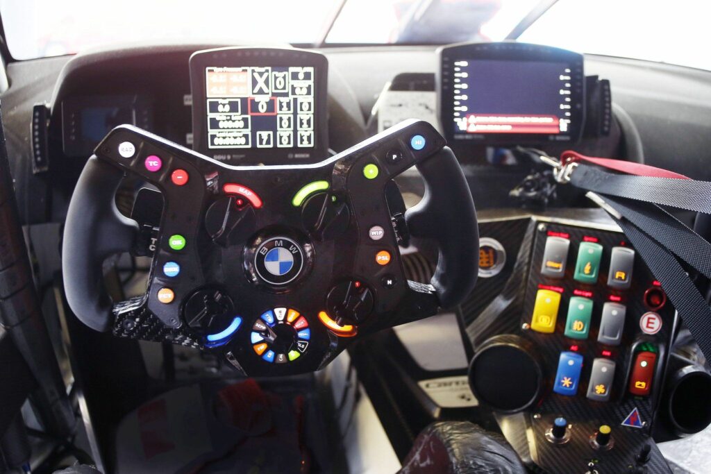
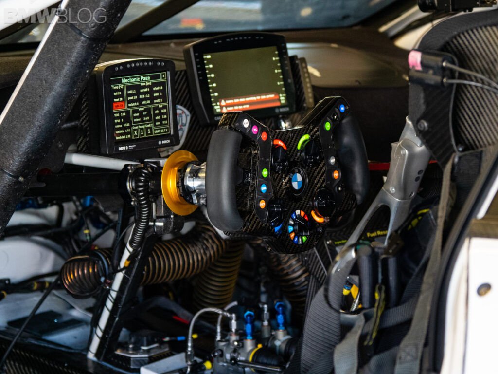
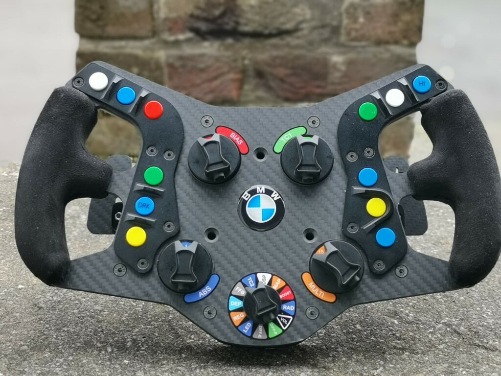
BMW M8 GTE – Wheel Build
The BMW M8 GTE is an endurance grand tourer (GT) car constructed by the German automobile manufacturer BMW. It was developed in late 2016 and made its competitive début in IMSA WeatherTech Sports Car Championship and FIA WEC for the 2018 season, and thus marking BMW Motorsport’s return to 24 Hours of Le Mans after a six-year hiatus. The M8 GTE, which replaced the ongoing BMW M6 GTLM at the end of the 2017 season, is based on the BMW M8. The car was unveiled on 12 September 2017 at the Frankfurt Motor Show, Germany.
The twin-turbo, V8 powered beast joins the already impressive lineup of GTE cars. With over 500 bhp, the flagship racing car from BMW competes around the world in series including the FIA World Endurance Championship and the IMSA Weathertech SportsCar Championship.
A front engine car, the BMW has already earned a reputation for being tough to pass due to its performance and size.


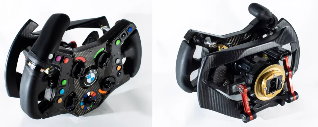


BMW M8 GTE – Wheel Build
This is a DIY wheel build project by Pokornyi Engineering where the DIY files are available on his website. The guides for the wheel builds from Pokornyi are very high quality and go through very detailed steps required to assemble the design for the average DIY enthusiast with minimal knowledge of wheel building. This article will supplement the Pokornyi guide by giving my experience during the building of this wheel.
The build guide is available here: https://pokornyiengineering.com/collections/diy-designs/products/m8-gte-design
This was written based on v1_20210107 version of the build guide.


Step 1 – Printing the 3D files
There are 19 files to 3D print with this wheel, 15 of these are printed on a regular filament 3D printer and 4 visible elements are recommended to be printed on an SLA resin printer. These can all be printed on a filament 3D printer but the finished surface quality will not be as good as a SLA printer.
- ButtonSupportLeft
- ButtonSupportRight
- Enclosure
- EnclosureInfillOverlap
- GripCup
- GripLeftFront
- GripLeftRear
- GripRightFront
- GripRightRear
- LogoTemplate
- PCBFix
- PCBHolder
- PCBHolderGuide
- ShifterLever
- ShifterMain
The 4 3d prints to print on a SLA printer are:
- ButtonPlateLeft
- ButtonPlateRight
- 4 x RotaryKnob
- SwitchKnob
WP 3D Thingviewer Lite need Javascript to work.
Please activate and reload the page.
Step 2: Ordering the carbon fibre parts:
I ordered the carbon fiber front plate from Michelle at Shenzhen GDC Tech Co., Ltd [http://www.szgdctech.com]. It was a reasonable cost, but the shipping is expensive so if you’re planning on ordering more carbon fibre parts it may be best to get them all together. I ordered the parts for the M8GTE and GTEPRO together to try to save on shipping.

Step 3: Ordering the Components
Electronics
I ordered most of the electronics from Mouser who had all components in stock. I wanted a higher indent on the encoders than the one linked on the build guide so I ordered PEC11H encoders to replace the PEC11R. (I first ordered CTS288 encoders but found out the hard way that these are not a direct replacement in size or electronic output).
The PEC11H has a much better tactile feel when rotating than the PEC11R, which is very light and can unintentionally rotate more clicks than intended. The PEC11H has a medium intent between positions but it does have noticeable play within the position. The encoders are something that I will replace later when I find a replacement that will still work with the same encoder output (this is proving difficult).
The 12 position rotary switch has very nice tactile feedback.
The components ordered from Mouser are below.
| Description | Mouser Part Number Manufacturer Part Number Description |
|---|---|
| Rotary Encoder with Ball Spring | 652-PEC11H4015FS0016 PEC11H-4015F-S0016 ROTARY ENCODER W/BAL |
| Rotary Switch 12 position | 10SM129 CK1029 1POL 12POS SOLDER |
| Buttons – Tactile 12×12 – Omron B3F-4055 | 653-B3F-4055 B3F-4055 12x12mm Std Ht .3 Hi |
|
Connector Plug – 4 pin – Circular DIN Connectors FEMALE RECEPTACLE 4 WAY *(This is different to guide to match a cable I had already) |
523-T3303320 T3303-320 FEMALE RECEPTACLE 4 |
| Basic / Snap Action Switches SPDT 5A OF 10g | 612-MS0850503F010S1A MS0850503F010S1A SPDT 5A OF 10g |
Other components:
| Additional Components | Description | Ordered From |
|---|---|---|
| STM32F103C8T6 | STM32 STM32F103C8T6 Minimum System Development Core Board For Arduino |
Ebay |
| Button Caps and switches | 25Pcs Tactile Push Button Switch Momentary Tact & Cap 12X12X7.3Mm Kit Arduino TU | Ebay |
| Threaded Inserts | 100PCS M3x6 Brass Cylinder Knurled Threaded Round Insert Embedded Nuts | Ebay |
| Wiring | AWG 22-24 | Amazon |
| Coiled USB Cable | High Quality Coiled USB Cable 55cm / 21 inches | Ebay |
| Micro USB to DIN connector ( soldered) | Micro USB Male to Dupont 5Pin Female Header Motherboard Cable Cord Adapter | Ebay |
| Swade Wrap for Grips | Carbins self adhesive fabrics for car interior styling color changing roof fabric good stretch 1.42*1 meter | AliExpress |
I ordered the STM32 board from China on ebay. When ordering, note that there are different types of board that look the same but have different specifications. The STM32F103C6T6 and STM32F103C8T6 will work for the .hex file for the BMW M8 wheel, however I ordered the STM32F103C6T6 for other projects and it did not have enough flash memory to install the .hex file
To flash the board, I ordered the ST-Link V2 Programming Unit mini STM8 STM32 Emulator Downloader M89 New from eBay. It worked without any problems.
The Micro USB Male to Dupont 5Pin Female Header Motherboard Cable Cord Adapter is used to connect the STMboard to the pin adapter – make sure it has a 90 degree connection to the micro USB because there is not enough space for a straight connection.


Step 4: Nuts and Bolts
This should have been an easy step because I usually order all bolts from accu.co.uk but after Brexit the only courier they will use for international orders charges about €30 in additional fees so I used eBay and aliexpress for ordering them instead.
One set of bolts missing from the guide are the 3 through bolts to connect the quick release to the wheel. These are M6x40mm so add these to the order!
Step 5: Preparing the 3D prints
The visible 3D filament printed components need to be sanded to give a good surface quality. Process per below:
120 grit > 2 coats of filler > 120 > 180 > 240 > 320 > 400 > 600 > 800 > 1000 > 1500
I sanded further up the grit scale than the guide asked but that is because I had this sandpaper available in a pack that I ordered.
After sanding these were coated in a couple of light sprays of matte black acrylic paint.
The SLA resin printed components were sanded lightly only where there were slight surface imperfections on the edges and coated directly with the matte black acrylic paint.
")
")
")
")
")
")
")
Step 6: Assembly
I first used the solder to insert the threaded inserts.
Glue in the buttons into the button holders. Snip the connectors on one side and solder the pins on the other side together. Solder wires from the pins and leave enough wire to connect to the board at a later stage.
Put on the button covers and bolt the button plate and button assembly to the wheel. Test fit the buttons and make sure they are not getting stuck and pass freely through the button plate. I had to use a 12mm drill bit turned by hand to clear paint and edges from the button plate holes to ensure the buttons were not obstructed. This was due to the button positions being slightly misaligned on the button holder when glued down because they are not a tight fit on placement to the button base.
[Update] This is an area that could also be improved in the design or when installing button bases. The 3d printed button holder has some tolerance so then the buttons are glued in place they do not perfectly align with the holes in the button plate. I oversized the button plate as noted above to correct this, however this has left some lateral movement n the buttons so they don’t feel as precise as the LMP wheel, which uses the same buttons but are mounted to a PCB and are perfectly aligned with the button plate. If doing this again, I would 3d print an insert so that there was no tolerance in the 3d printed button base, and not oversize the holes in the button plate to make sure they are a good fit with no lateral movement.
")
")
")
Soldering
This is what the wiring looks like after the soldering is done. I connected the button and position switch wiring on the 12 position switch. There are a lot of wires so try to keep the wiring as short as possible to make the connections.
I soldered the encoders next and glued them in place. They need to be glued because there is not enough thread to protrude through the 5mm carbon plate.
Next was the shifters. I used a wire connector for these to be able to disconnect if I did need to take the backplate off again.
")
")
")
")
")
")
")
")
")
")
")
")
")
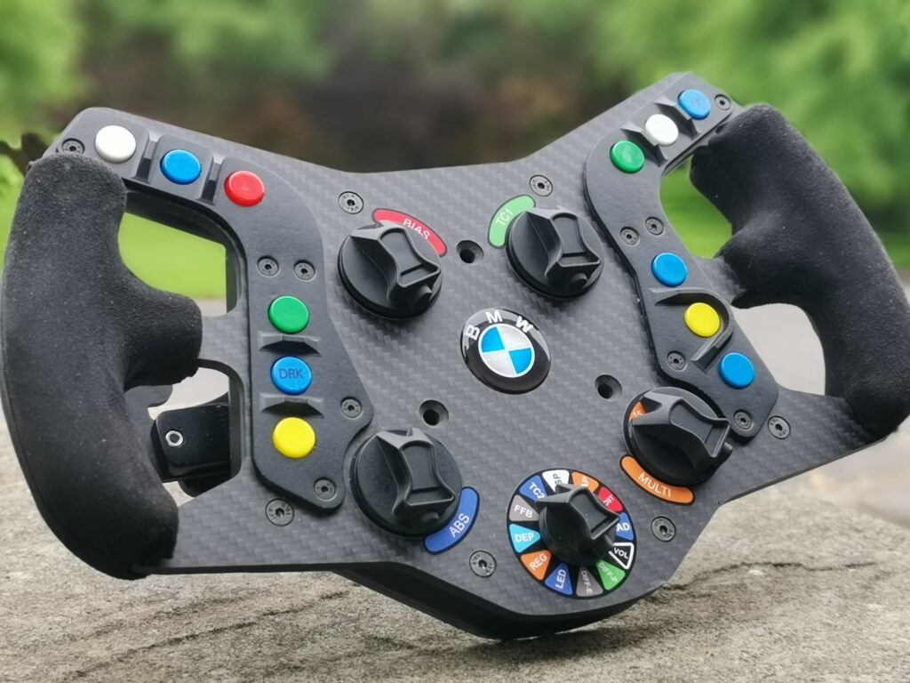
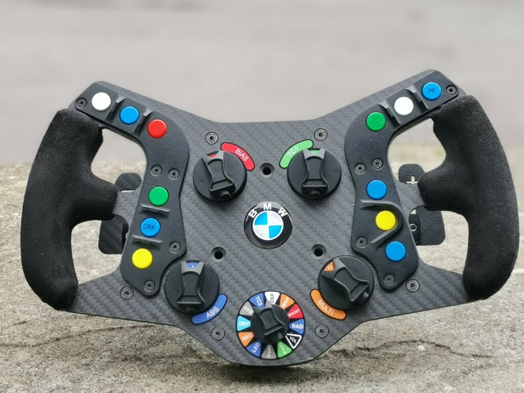
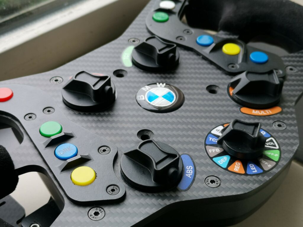
Stickers/Decals
The stickers that come with the DIY files are in PDF so are not editable. The encoder switches are 20 position stockers however the recommended encoders are 12 positions so the stickers may not be accurate to the current BOM. I used different encoders with 16 positions, so I needed to create updated stickers.
The main dial stickers are 34mm diameter and the position switch is a 42mm diameter. The inner hole in the dial stickers is 7mm (the encoder is 6mm) and the position switch has an inner hole of 16mm because there is a nut on the faceplate side and needs to be cleared with the sticker. I struggled to get the quality I needed with my inkjet stickers and was not happy with the results so I ordered the stickers from simracingstickers.co.uk, they re-made the stickers in a vector format, printed and cut them and the quality was great.
The provided PDF button stickers are all in transparent black however the real wheel uses different colours.
")
")
")
")
")
Grips
Covering the 3d printed grips in swede is relatively straightforward because the grips are small enough it does not need much stretching. It is however a challenge at the ends where excess swede needs to be trimmed back.
The first step was to superglue the nuts into the holes on the front grip. After that the hole caps need to be superglued in. These were recessed on my grip, so I added some filler on top and sanded it down flush with the handle.
I then covered the front section of the grips in swede.
The back side has the screws in it so the holes can’t be covered before they are placed. I put the 2 screws into the handle then added the swede wrapping. When finished I made a small hole to for the Allen key inside for final tightening.
These back holes could be filled after, but you will not have access to the screw if this is done.
The wrapped grips look ok but I think they feel a little bulky. I intend to revise the grips by printing in rubber flexible resin similar to the LMPPRO wheel. More information will be added when this is complete so check back later.
")
")


Final Thoughts…Its a DIY wheel, its never finished
There are a couple of things that id like to improve on this wheel;
- Grips – I intend to re-print the grips in F80 Resione.
- Buttons – Get epoxy dome stickers for the buttons in original colours and replace the buttons with resin printed transparent buttons.
- Replace the encoders with ones that have zero play in position. (I’d like to swap them out with CTS288 encoders but these have a different output)
- The threaded inserts in the rear gear shifters have started to slip. Replace the threaded inserts so that the fixing is from the back instead of from the inside of the wheel, and change to a nut and bolt arrangement on this part.