GTE PRO (911 RSR) – The Car
The first mid-engine Porsche 911 is the RSR and it features a 4.0 liter, normally aspirated engine that produces 510 hp. The car is raced worldwide in the LM-GTE category in series including IMSA, WEC and Le Mans.
The 911 RSR is Porsche through and through. With its aggressive styling cues and familiar silhouette, the flat-6 six engine literally screams at you when you accelerate out of corners. Weighing in at a mere 1,243 kg (2,740 Ibs), the RSR is a well-balanced race car with massive brakes for unrivalled stopping power and a newly designed 6-speed sequential gearbox that allows for lightning changes up and down through the gears.
The 911 RSR competes against its GTE rivals including Ferrari and Ford.

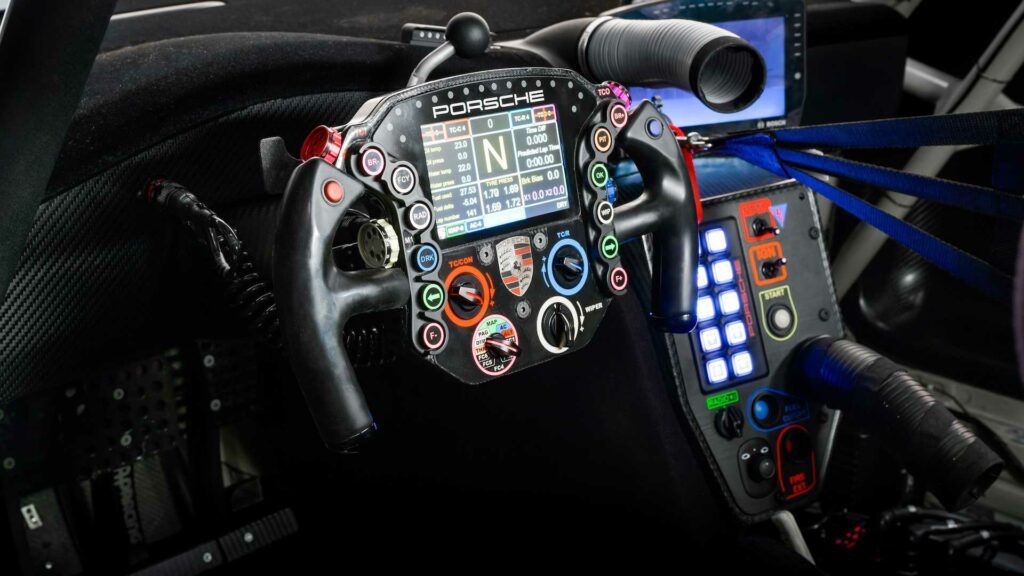


Porsche 911 RSR (GTE) – Wheel Build (Superseded by the V2 Version)
This is a DIY wheel build project by Pokornyi Engineering where the DIY files are available on his website. This version of the wheel have been superseeded by V2 version and are no longer available for purchase, however I had the components already purchased for the V1 version so have added the build process. This article will supplement the Pokornyi guide by giving my experience during the building of this wheel.
The V2 version of this wheel are located here: https://pokornyiengineering.com/collections/diy-designs/products/gte-pro-diy-files
This was written based on GTEPRO_v2.2_20220207 version of the build guide.
Porsche 911 RSR BOM
The bill of materials (BOM) for this wheel are contained in the DIY files received when they are purchased. Note that some electronic components are shown on the main BOM, and others are shown on the PCB BOM so they need to be added to get the total number of components.
1.0: Printing the 3d files
Printer settings for the Prusa MK3S
Mainhousing-bottom, Mainhousing-top – From the previous LMPPRO wheel I was not entirely happy with the print settings for the supports and the artefacts left when removing them, causing the backplate to be slightly higher than the back of the 3D print so I spent some time adjusting the support settings for the man housing print to make it easier to remove the supports. My settings are below:


Other 3d printed components:
BackPlateStrength – Not used. This clashes with the screws for the rear adapter so I did not install this piece. I found the wheel had sufficient stiffness without this additional support.
ButtonPlateL and ButtonPlateR – Printed in SLA.
Grip_cup – Not used, my grips have open screw holes.
Grip-left-front, Grip-left-rear, Grip-right-front and Grip-right-rear – The grips are printed in black SLA. I would print these in Resione F80 if doing it again. Note that the grips do not meet in the middle and leave a large gap (approx 2mm) so they can be covered in swede wrap. I do not intend to wrap them so this gap is annoying and will need to be re-modelled when re-printing the grips.
magnedHolder – FDM printed with 100% infill. This needed to be filed down slightly to fit in the final carbon fibre part.
Rotary A, B, C, D, RotaryKnob, RotaryKnobV2 – I did not use any of these knob models because they are not based on the IRL car knobs. The IRL knobs were modelled by other community members and printed in SLA.
shifterArm, shifterMain – FDM printed with 100% infill. This needed to be filed down slightly to fit in the final carbon fibre part.
shifterPaddle, shifterSide, shifterTop – These are carbon cut parts and are not printed.


2.0: CNC parts
I ordered the CNC parts from GCG, the prices are reasonable however the shipping and customs bring up the price significantly. The cut prices are shown below.

3.0: PCB Assembly
The PCB version I used is V2.1. Most of the surface mounted components are already soldered onto this board. The remaining components to solder were the buttons, encoders and the connectors for the switches and non-PCB mounted components.
Soldering these components is daunting for a beginner DIYer but as more components are added to the PCB, the more confident you will feel. Leave the tricky ones that are close to other components to the end when confidence is higher.
TIP: I found that using additional flux to connections really cleaned them up and made the solder flow into the connection.

Soldering Buttons
There is a note in the guide about adding a spacer below the button when soldering onto the PCB to raise the height of the button. I did not do this because I was not sure where the button height would end up, but after assembly I noticed that the buttons are below the outer surround of the button guards so preferably they would be raised up to be flush with the surround. If doing it again I would add the 1-1.5mm spacer to increase the button height. As a workaround, Ill probably add clear epoxy domed resin button caps which will raise the button height.
Flashing the PCB
The PCB is flashed using the four STM32 pins on the PCB connected to a STLINK V2 programmer. This programmer needs to be purchased (8 euro) from ebay or similar. Also, remember that the USB connection (GX12/16) and the STLINK V2 need to be connected to the PCB to flash the firmware to it.
When these are connected, open the ST-Link Utility and open the .hex firmware file provided in the downloaded files from PE. I have the v2 version of the PCB so choose the version that you have. The board will be detected and then upload the .hex file to the board.
Next you need to flash the ATmega chip with a bootloader. I missed this step and could not figure out why Simhub was not detecting the LEDs. There is a separate guide to loading the bootloader from PE that requires an Arduino UNO as a programmer. See link below.
Luckily, I had an Arduino UNO in a drawer so I used that to load the bootloader. (I did not have to do this step with the LMPPRO wheel so I was confused by the GTEPRO manual). Follow the manual for uploading the program sketch to the Arduino, then wire the Arduino to the GTEPRO PCB as shown on the manual, change the board to Arduino Nano, programmer to ATmega328P and programmer to Arduino UNO, then Burn Bootloader. This will add a program to the chip so it can be found by Simhub later.
Simhub is then used to create the firmware for the ATmega328P. Follow step 10 on the PE manual for this. Another thing to note here is to select the new bootloader from the dropdown option in Simhub instead of the old version. That’s another 30 mins ill never get back!
PE does not give LED light templates for the car, but luckily there is a discord user called Yoep De Ligt that has created a template for almost all cars, and it automatically detects the car your driving to sync the lights. It really is an impressive piece of work. The template can be downloaded from his discord at this link: https://discord.com/invite/ejJTXSuMaM


The Nextion Problem
The parts list for this old version of the wheel includes a 5 inch Nextion display. I knew the Vocore screen was recommended for new builds but this wheel design was built for the Nextion display and includes all of the template files so I decided to stick with the Nextion display. This turned out to be a waste of money and time because the current Nextion displays do not seem to be supported by Simhub anymore. (https://github.com/SHWotever/SimHub/wiki/Nextion—End-of-support)
My old display in the LMPPRO wheel still work fine but as soon as I tried to upload firmware to the new display I got an error that the firmware would be updated, followed by an error on the screen that the file was invalid. I did manage to get the .HMI file to upload to the screen by downloading the latest Nextion Editor from the Nextion website, but Simhub would not send any of the telemetry to the screen.
After countless hours of troubleshooting I gave up, I think the only thing to do is to replace this screen with a Vocore screen, which will also need an additional USB hub soldered into the wheel. So although the screen looks finished, the screen is currently just a pretty picture.

4.0: Wiring
The guide is clear on how to wire the encoders and switches so I will not repeat it here, the display is also shown clearly with the main mistake is not wiring the TX to RXD and RX to TXD. However if your using a newer Nextion display you will have other problems – see the paragraph above.
USB Wiring
USB wiring diagram is shown to the PCB however the pin output to the GX16 connection is not shown on the guide. The pin output is shown below:
PIN 2 = D+ = Green
PIN 1 = D- = White
PIN 3 = GND = Black
PIN 4 = 5+ = Red

5.0: Decals/Stickers
The decals which come with the wheel do not match the IRL wheel so these are in progress.