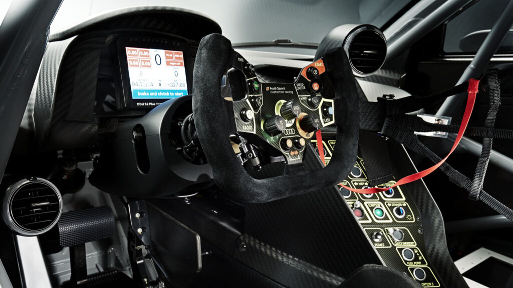
Audi R8 LMS – The Car
The Audi R8 LMS GT3 ranks among the most successful GT3 cars with more than 200 international wins in events such as the Bathurst 12 Hours and Nurburgring 24 Hours, along with back-to-back championships in the 2014 and 2015 Blancpain Endurance and Blancpain GT Series. In contrast to its all-wheel drive road going version, the R8 LMS GT3 is built by Audi Sport and quattro GmbH to comply with the rear wheel drive only GT3 regulations. However, the superb balance and impressive power to weight ratio of the R8 LMS GT3 have made it a winner in virtually every series in which it’s competed.


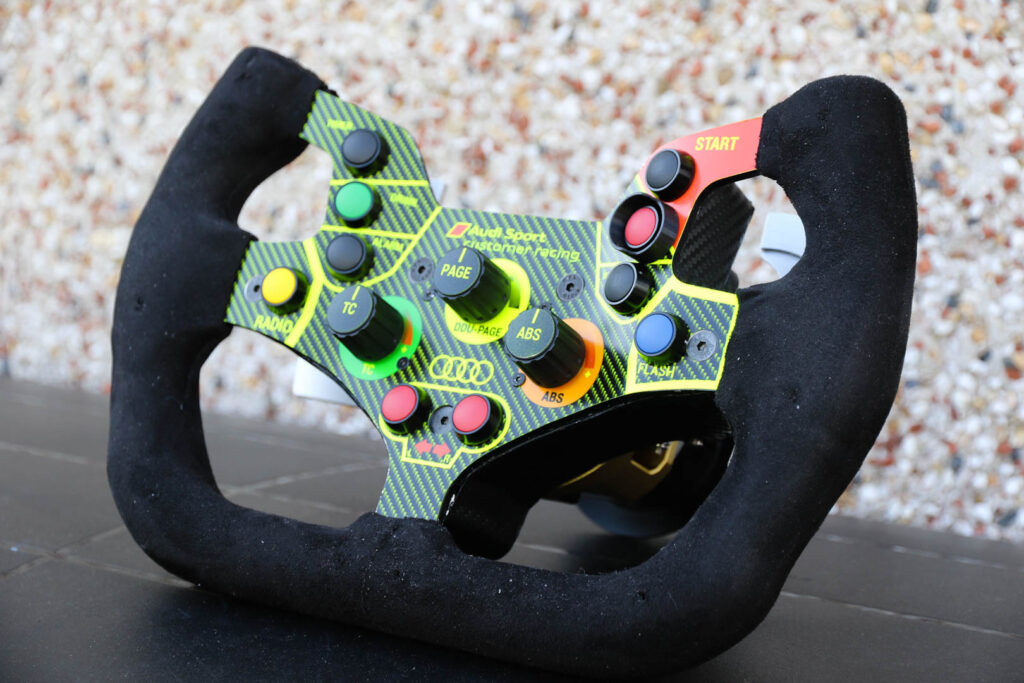
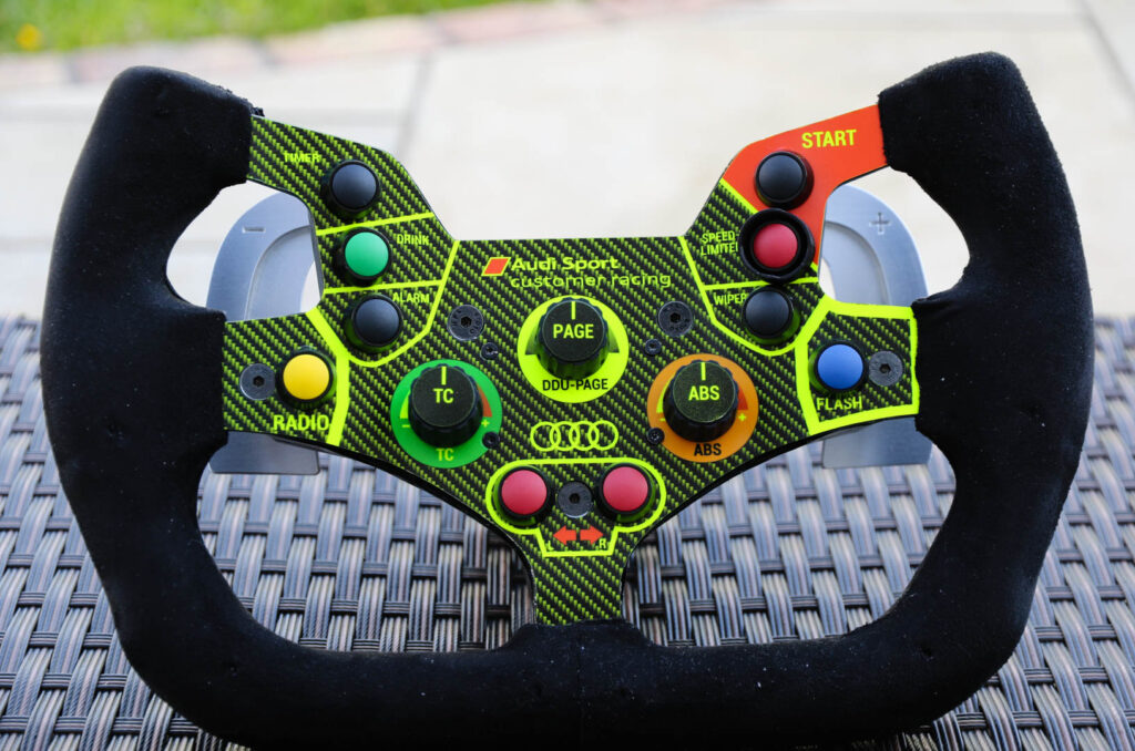
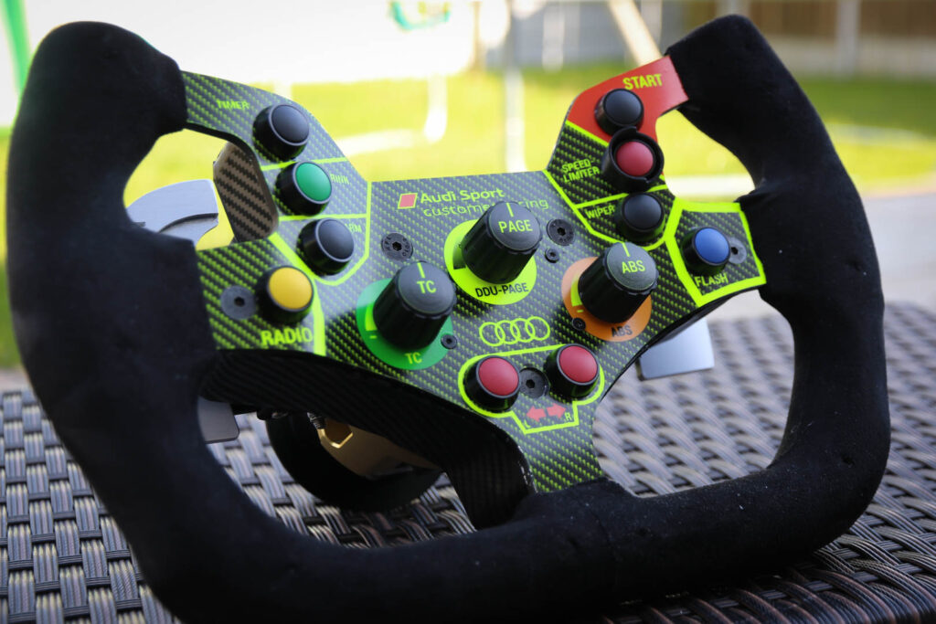
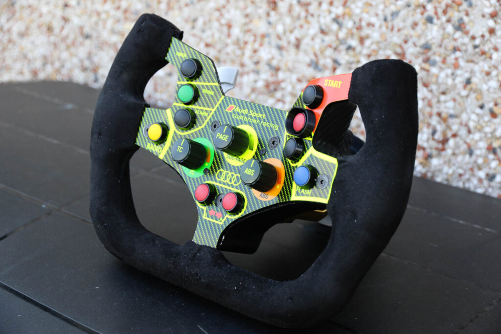
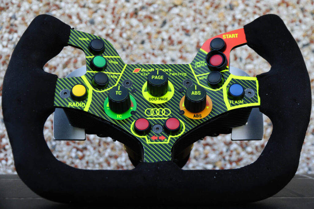
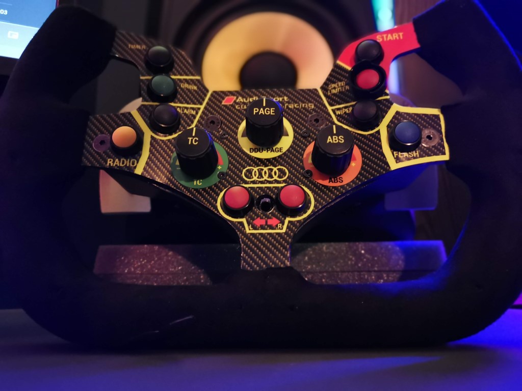
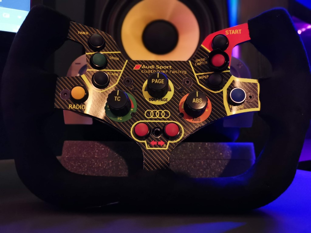
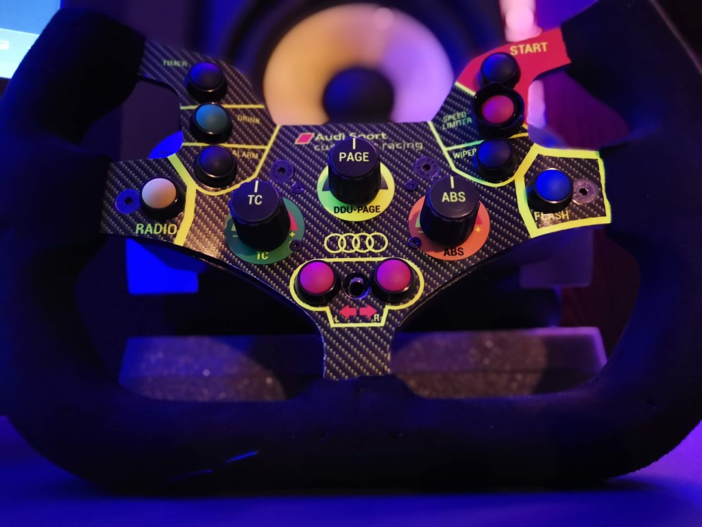
Audi R8 LMS – Wheel Build
This is a DIY wheel build project uses the Turn R8 LMS DIY sim racing wheel as a base for grips and electronics, but the modelling is heavily modified to include the profiled front plate similar to the real wheel. The Turn DIY files are now available for free at this link: https://www.thingiverse.com/thing:5173146


")
")
")
Audi R8 LMS BOM
| Number | Type | Part Name | Description | Image | Quantity | Link |
|---|---|---|---|---|---|---|
| 1 | Electronics | USB Controller | Leo Bodnar BU0836A-NC | 1 | https://www.leobodnar.com/shop/index.php?main_page=product_info&cPath=94&products_id=219 | |
| 2 | Electronics | BU0836A | Breakout Board | 1 | https://www.leobodnar.com/shop/index.php?main_page=product_info&cPath=94&products_id=274&zenid=91af8deb34af5b96a8e8839eca71b410 | |
| 3 | Electronics | CTS288 | Encoders | 3 | https://www.leobodnar.com/shop/index.php?main_page=product_info&cPath=98_75&products_id=243&zenid=91af8deb34af5b96a8e8839eca71b410 | |
| 4 | Electronics | Buttons | Encoder Knobs and Caps | 3 | https://www.leobodnar.com/shop/index.php?main_page=product_info&products_id=198&zenid=91af8deb34af5b96a8e8839eca71b410 | |
| 5 | Electronics | Lumberg SV 40 | Lumberg, SV 4 Pole M16 Din Plug, DIN EN 60529, 5A, 250 V ac IP40, Screw On, Male, Cable Mount | 1 | https://ie.rs-online.com/web/p/din-connectors/5336742 | |
| 6 | Electronics | Coiled USB Cable | High Quality Coiled USB Cable 55cm / 21 inches | 1 | https://www.ebay.ie/itm/114757154937 | |
| 8 | Bolts | M2.5 x 25mm Flathead | 4 | |||
| 9 | Nuts | M2.5 Locknut | 12 | |||
| 10 | Bolts | M4 x 12mm Flathead | 4 | |||
| 11 | Bolts | M5 x 15mm Flathead | 2 | |||
| 12 | Bolts | M5 x 45mm Flathead | 3 | |||
| 13 | Bolts | M5 x 25mm Cap head | 6 | |||
| 14 | Bolts | M5 x 20mm Cap head | 2 | |||
| 15 | Nuts | M5 Nylon Locknut | 11 | |||
| 16 | Electronics | KFV 40 | Lumberg, KFV 4 Pole M16 Din Socket, DIN EN 60529, 5A, 250 V ac IP40, Screw On, Female, Panel Mount | 1 | https://uk.rs-online.com/web/p/din-connectors/5332706 | |
| 20 | Electronics | Buttons | Alternative Buttons - See Notes on Buttons -12mm domed Momentary Zinc-aluminium Alloy Metal Push Button Switch Screw terminal push button Car Auto Horn Door Bell Switch | 10* | https://www.aliexpress.com/item/32838892858.html?spm=a2g0o.order_list.0.0.eb691802iWY5e8 | |
| 21 | Fabric | Grip Wrap | Carbins self adhesive fabrics for car interior styling color changing roof fabric good stretch 1.42*1 meter | 1 | https://www.aliexpress.com/item/32751670715.html?spm=a2g0o.order_list.0.0.eb691802iWY5e8 | |
| 22 | Magnets | Magnets | Shifters - Magnets 12mm x 5mm | 4 | https://www.ebay.ie/itm/124153728298 | |
| 23 | CF Wrap | 3D CARBON FIBRE VINYL SIZE 300MM x 1520MM BLACK CAR WRAP | 1 | https://www.ebay.ie/itm/202344368785 | ||
| 24 | Electronics | Wiring | Dupont Jumper Wire Ribbon Cable Female-Female | 40 | https://www.ebay.ie/itm/163069904597 | |
| 25 | Decals | Decals | Decals - Simstickers | 1 | ||
| 26 | Bolts | Shifters - M4 x 40mm Socket Head | 2 | |||
| 27 | Bolts | Shifters - M3 x 5mm Socket Head | 4 | |||
| 28 | Nuts | Shifters - M4 Nylon Locknut | 6 | |||
| 29 | Nuts | Shifters - M3 Hex | 4 | |||
| 30 | Electronics | D2HW-BR213MR | Shifters - SWITCH SNAP SPST-NO 100MA 125V - Right | 1 | https://www.mouser.ie/ProductDetail/Omron-Electronics/D2HW-BR213MR?qs=B3tblJ0Nlt%252B6WWYd7L8Jvg%3D%3D | |
| 31 | Electronics | D2HW-BR213ML | Shifters - SWITCH SNAP SPST-NO 100MA 125V - Left | 1 | https://www.mouser.ie/ProductDetail/Omron-Electronics/D2HW-BR213ML?qs=B3tblJ0Nlt9XCHMeTTag%2Fg%3D%3D | |
| 32 | Shifter | Shifter Modified STLs | Shifter Modified STLs | 2 | https://diysimracing.com/wp-content/uploads/2017/01/Shifter-STLs.zip | |
| 33 | ||||||
| 34 | Front Plate | Front Plate Cut Drawing | Drawing for the Front Plate for CNC | 1 | https://diysimracing.com/wp-content/uploads/2017/01/Wheel-Cutout.zip |
Step 1: Printing the 3D files.
All of the 3D printed components are modified from the original Turn .stl files to suit the changes to this wheel. There are 8 files to 3D print with this wheel, these were all printed on a filament 3D printer. The button guard is the only part visible from the front of the wheel which would benefit if you have access to use a SLA printer.
- Button Guard (SLA resin)
- Grips
- Left Front Grip
- Left Rear Grip
- Right Front Grip
- Right Rear Grip
- Shifter
- Paddle – CNC’d from Aluminium
- Shifter enclosure and lever
- Rear Enclosure
Step 2: Ordering and Cutting the Aluminium Front plate:
The first aluminium front plate I ordered was 3mm grade 6082 T6. It cut fine but when I tried to bend it, it broke suddenly because this is a toughened grade of aluminium. I decided it would be better to use 5083 which is a non-toughened grade of aluminium and would not need heat applied to bend it.
")
")
")
")
I ordered a 4mm plate (100mm x 150mm) in grade 5083 and this was much more convenient to bend, I could take my time and make sure it was bending correctly and to the correct amount without worrying about the heat I needed to apply.
The reason I ordered 4mm instead of 3mm was that this was all that was in stock locally on the ebay store. This was just thin enough to fit the nut from the buttons on the back side of the plate.
")
")
")
Step 3: Ordering the electronics
The electronics to order are on the BOM above. There are 10 buttons, 3 encodes and 2 shifters connected to a leo bordnar electronics boards which is then connected to the 4 pin connector on the outside of the wheel. A USB to 4 pin connector is used to connect it to your PC.
Buttons:
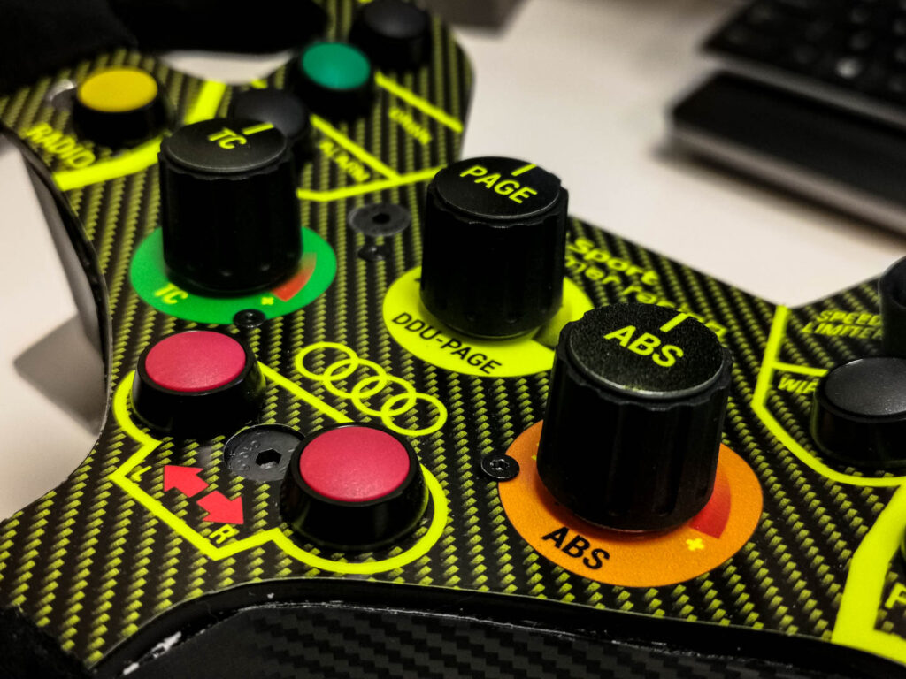
The original APEM buttons that are used on the real wheel were out of stock when I was building the wheel, and they are a hefty €20 approx for each button which would be €200 in buttons alone for this wheel. I did not want to skimp on quality, but the APEM buttons were not due in stock for another year, so another recommended button was the Otto P9 buttons which were approx. €15 each. I ordered the elevated specification of P9 button to match the original as much as possible however do note that these have a domed top so decals do not fit them.
I intended to use the P9 buttons but decided to order a full selection of cheap buttons from ali-express to check out the tactile feedback and quality of the cheaper buttons, I ordered 4 different types but to my surprise one of these types looked very well and had a nice tactile feedback, it did not have as high of force as the P9 buttons but it didn’t sway as much laterally during the press as the P9, which was something I disliked about them. This is probably because the P9 spec that I ordered extends above the surround of the button, and if I ordered the button type that does not extend above the surround it might not move as much laterally but comparing the P9 to the ali-express button, I favored the ali-express button, and this is what I used on my wheel.
To get a second opinion I also checked with 4 others on their preferred buttons and they all chose the ali-express ones so this confirmed my choice. The best or worst part of this is that the Ali-express buttons cost €10 for 10 buttons – that’s €10 instead of €150 for buttons and it was not a compromise as I still have €150 of Otto P9 buttons in my drawer.
The other 3 types of Ali-express buttons had a spongy cheap feel, so these were not used.
Step 4: Nuts and Bolts
I ordered the nuts and bolts from ACCU. But I have recently stopped using them due to delivery and custom charges, so I order bolts from ebay and aliexpress and they usually come directly from China.
Preparing the 3d prints:
The visible 3D filament printed components need to be sanded to give a good surface quality. Process per below:
120 grit > 2 coats of filler > 120 > 180 > 240 > 320 > 400 > 600 > 800 > 1000 > 1500
I sanded further up the grit scale than the guide asked but that is because I had this sandpaper available in a pack that I ordered.
After sanding these were coated in a couple of light sprays of matte black acrylic paint.
Bending the Front Plate
To make the profile of the front plate, a bending rig was made from aluminium profile, the pressure was applied with a bottle jack and a 90 degree aluminium angle between the two supports. The first two bends can be made in this way, carefully increasing pressure and watching the plate bend until the correct angle is achieved.
The two other bends to the outside of the wheel cannot be done in the same rig because the first bend in the wheel obstructs the bending rig. To make the outer bends, the wheel was placed in a vice and manually pressed until the correct angle is achieved.
This is a manual process therefore the wheel backplate will not fit perfectly into the bent front plate. This is covered later in the design where additional filler will be used to seal any gaps between the backplate and the frontplate.
")
")
")
")
")
")
")
Test Fitting
Bending the front plate also introduces a manual tolerance to the assembly of the wheel so its necessary to test fit the grips, buttons and electronics before proceeding. When it fits correctly the front plate can be painted. I used a matt black acrylic paint.
")
")
")

")
")
")
I used four standoff screws with 3d printed spacers to mount the Leo Bodnar and matrix boards, just above the encoder housing. The 3d printed bracket was used to check clashes with the rear housing before the full back plate was was printed and fitted. The back of the wheel has 3 components stacked (encoder, matrix board and leo bodnar board) so the clearance to these components is minimal but important to check before wiring. If there is a clash, try to reduce the spacing between the boards and encoder because the distance between the boards is set based on the pin headers.
")
")
")
Electronics and Wiring
I added 90 degree dual pin headers to the matrix board which were turned into the gap between leo bodnar and matrx board. These pin headers are connected to the buttons with standard Dupont jumper wires. I ordered the buttons with screw terminals to make these connections simpler. The photo below shows the finished wiring.
An example for the wring diagram for buttons and encoders is shown in the photos below. For more information on the terminals used see the leo bodnar website.
")
")
")
")
")
")

Grips
The grips are 3d printed with suede/alcantara covering. These are prepared in two half’s for each side of the wheel and fixed with 3 nuts and bolts through the wheel.
")
")
")
Decals
The main wheel cover decal was printed directly onto a florescent yellow page, which turned out very good. Initially I printed the front sticker with an inkjet printer then laminated it and cut it out but I was not happy with the results due to delamination during cutting and the print quality of the inkjet printer onto the florescent page, so I reached out to Paul from simstickers.co.uk who did a much better job and it looks amazing.
")
")
")
")
")
")
Shifters
The shifter pedals are CNC machined from aluminium and the shifter supports are 3d printed. The 3d printed parts were strengthened, thickened to reduce the amount of flex and a larger magnet added to increase the tactile feel of the shifter. The modified shifter STLs and CNC cut files are included in the link in the BOM.
")
")
")
")