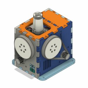
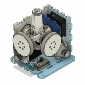
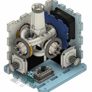
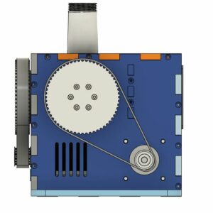
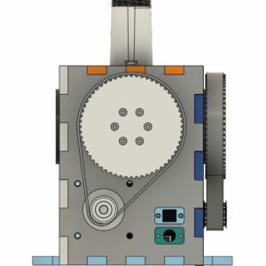
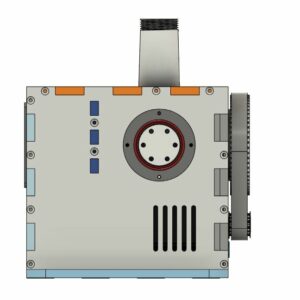
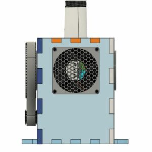
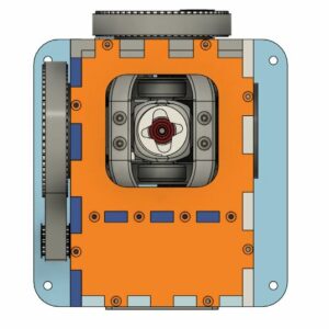
VP Force Rhino Force Feedback Joystick Base
The VPForce Rhino is a force feedback joystick designed for flight simulation. It has several key features:
- Force Feedback: The VPForce Rhino provides realistic force feedback, allowing you to feel the effects of turbulence, G-forces, and other flight conditions.
- Dynamic Center: Unlike traditional joysticks with a fixed center position, the VPForce Rhino dynamically adjusts its center point based on the aircraft’s behaviour. This feature is especially useful for aircraft like the F-14 or Apache, where the center position can shift during flight.
- Trim Simulation: The joystick includes force trim simulation, which replicates the feel of adjusting trim tabs on an aircraft. This is crucial for maintaining stable flight.
- Helicopter Support: Helicopter enthusiasts will appreciate the VPForce Rhino’s accurate force feedback for helicopter controls, including collective pitch and cyclic movement.
- Customizable: You can fine-tune the force feedback settings to your preference, tailoring the experience to different aircraft types.
VP Force Rhino Force Feedback Joystick Base – DIY Build
You can get the VPForce Rhino through a few different avenues:
- Order Directly: You can order the VPForce Rhino directly from VPForce, but the delivery time can be 1-2 years (this is reducing so check the discord for latest waiting times). Keep in mind that the base comes without a power supply, so you’ll need a standard 180W laptop power supply with a 5.5mm DC connector.
- DIY Build: VPForce offers a DIY kit for the Rhino FFB system including the motors and the main controller board in a package with no pre-order time. This kit allows enthusiasts to build a plug-and-play force feedback joystick with custom build plans developed by the community. This is the method shown here to build this unit.
Remember to explore the options that best suit your preferences and availability!
I followed the DIY build which is based on the 3D printed DIY kit from Mabo1972s and protomaker964 design on Github using the DIY FFB kit: 57BLF03 x2 + USB – 299 € (+ VAT) kit purchased from the VP force website (https://vpforcecontrols.com/).
Introduction and Notes
The steps below are from the assembly guide revision 13 from protomaker964 GitHub page with additional comments in blue where I have added extra comments. The guide was on revision 10 when I started my build so the comments below relate to that specific build guide revision.
- This instruction set is for a DIY clone version of the VPForceControls force feedback
joystick base. - This build is based on the motor kit from VPForce, 2x57BLF03 + USB kit.
- Belt sizes are based on 74tx12t pulleys.
- All 3d Printed parts are adapted from the Mabo1972s design Github. https://github.com/mabo1972/FFB-Joystick-Base-Plywood.
- Links for parts purchase have not been provided due to possible vendor changes and people needing to source from many countries. Therefore I have tried to use the most correct and common names for parts.
- Parts have been sourced from Amazon, Digikey and the Nutty Company, but can likely be found elsewhere.
- All instructions are based on the included parts list and required 3d Printed parts in this guide and Github.
- These instructions include the 20 degree throw limiters which can be omitted if desired, and the spacer printed to then mount the boot assembly.
BUILD NOTES
- For the panel screws other than the mid panel, 8mm length will work, but 12mm will give you a better bite
- The E-Stop button interrupts the POSITIVE side of the power to the motors via the Mainboard
- POLARITY MATTERS. Pay attention to motor power connections!
- Motor data cable polarity is already correct with included cables. BE SURE THEY ARE PLUGGED INTO THE PROPER DATA PORT FOR EACH MOTOR. Motors are labelled.
- The USB connector in the VPForce kit is already terminated properly. Just plug it into the proper port on the main board.
- CLEAN UP ALL PRINTED PARTS and test fit. ESPECIALLY THE BEARING POSTS AND GIMBAL ENDS.
- Screw quantities listed in the Parts List are MINIMUMS.
- It does not hurt to pre-tap the gimbal parts screw holes prior to assembly
These instructions assume you are familiar with things like bearings, soldering, basic circuit wiring and 3D printing.
Watch the following video for some basics about the kit from VPForce:
Parts List
VP Force Rhino - Electronics
| wdt_ID | Quantity | Description | Link |
|---|---|---|---|
| 1 | 1 | 2x57BLF03 + USB kit from VP force | https://vpforcecontrols.com/ |
| 2 | 1 | Cuedevices MD-50PL100 is required to terminate grip connection | https://eu.mouser.com/ProductDetail/CUI-Devices/MD-50PL100?qs=WyjlAZoYn51%2FflnEwf%2F6yQ%3D%3D |
| 3 | 1 | XH2.5 JST connector kit - 2P for Fan and 5P for Grip Wire | |
| 4 | 1 | 22mm Latching Emergency Stop Push Button | |
| 5 | 2 | 10K Ohm Rotary Potentiometer | |
| 6 | 1 | 80mm x 15mm PC cooling Fan | |
| 7 | 1 | 5.5mm x 2.1mm 2 Pin DC Power Female Panel Mount Jack Socket Connector | |
| 8 | 1 | 20VDC 9a Power Supply with 5.5mm male plug |
VP Force Rhino - Bearings, Screws and Mechanicals
| wdt_ID | Quantity | Description | Link |
|---|---|---|---|
| 1 | 8 | 15x24x5mm 6802RS Bearing (Gimbal Pillow Block Bearings) | |
| 2 | 2 | 5x16x5mm F625ZZ Flanged Bearing (Core Joint to Stick Adapter Bearings) | |
| 3 | 4 | 40x52x7mm 68082RS Bearing (Gimbal Arm to Case Bearings) | |
| 4 | 1 | M5x60 Socket Head Screw (Stick Connector to Core Joint) | |
| 5 | 2 | M5 Nut (Stick Connector to Core Joint) | |
| 6 | 3 | M5 washer (Stick Connector to Core Joint) | |
| 7 | 4 | M5x10 Button Head Socket Cap Screw (Stick Core to Pillow Block Bearings) | |
| 8 | 8 | M5x10 Button Head Socket Cap Screw (Stick Connector to Gimbal Pillow Blocks) | |
| 9 | 12 | M4x35 Socket Head Screw (74T Pulleys) | |
| 10 | 4 | M4x35 (Boot Clamp Assembly) | |
| 11 | 12 | M4 Nut (74T Pulley to Main Gimbal Mounts) | |
| 12 | 24 | M4 washer (74T Pulleys) | |
| 13 | 34 | M4x12 Flat Head Socket Cap Screw (Case Edges) | |
| 14 | 4 | M4x12 Socket Head Screw (Top Panel Cover) | |
| 15 | 8 | M4x8 Flat Head Socket Cap Screw (Top Panel, Side Panels to Mid Panel) | |
| 16 | 8 | M6x16 Button Head Socket Cap Screw (Motor Mounts) | |
| 17 | 20 | M3x16 Socket Head Screw (Bearing Retainers and Boot Collar) | |
| 18 | 4 | M3x4 Socket Head Screw (Mainboard Mount) | |
| 19 | 4 | M3x30 Socket Head Screw (Cooling Fan) | |
| 20 | 16 | M3 Nut (Cooling Fan and Bearing Retainers) | |
| 21 | 4 | M3 washer (Cooling Fan) | |
| 22 | 2 | HTD-15 12tooth Aluminum Pulley 8mm Bore WITH GRUB SCREWS) (2Pcs ⋅ 8mm ⋅ 5M12T /16mm) | https://www.ebay.ie/itm/186011257811 |
| 23 | 1 | 420-5M-15 HTD 420mm Timing Belt (Roll) | https://www.ebay.ie/itm/373723139886 |
| 24 | 1 | 465-5M-15 HTD 465mm Timing Belt (Pitch) | https://www.ebay.ie/itm/373723139886 |
VP Force Rhino - Screw Table
| wdt_ID | Description | 4 | 8 | 10 | 12 | 14 | 16 | 30 | 35 | 60 | Nut | Washer |
|---|---|---|---|---|---|---|---|---|---|---|---|---|
| 1 | M3 Socket Head | 4 | 4 | 20 | 4 | 16 | 4 | |||||
| 2 | M4 Socket Head | 4 | 16 | 12 | 24 | |||||||
| 3 | M4 Countersunk Head | 8 | 34 | |||||||||
| 4 | M5 Socket Head | 1 | 2 | 3 | ||||||||
| 5 | M5 Button Head | 12 | ||||||||||
| 6 | M6 Button Head | 8 |
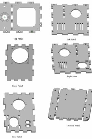
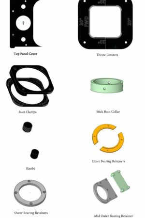
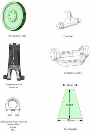
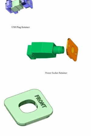
Printed Parts Reference
Assembly
Electrical Connections
- 5pin mini din soldered to 5pin JST for grip buttons
- Fan(s) soldered to 2pin JST plug and connected to main board
- Potentiometers connected to 3pin JST on main board
- Power positive soldered to E-Stop switch and then connected to main board terminal
- Power ground soldered to power plug and then connected to main board terminal
- Motor Power leads connected to main board terminals
- Motor Data leads plugged into corresponding 2pin JST on main board
Motor 1 is the Roll axis: Motor 1 = Roll
Motor 2 is the Pitch axis: Motor 2 = Pitch
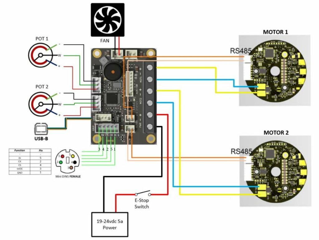
I was on step 11 before I started looking at the electronics so don’t feel you need to get this all done now, you actually need to route some of the wires before you crimp connectors so skip this section and come back to it when its ready to install.
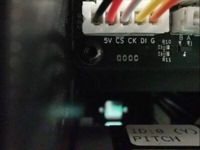
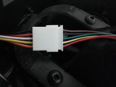
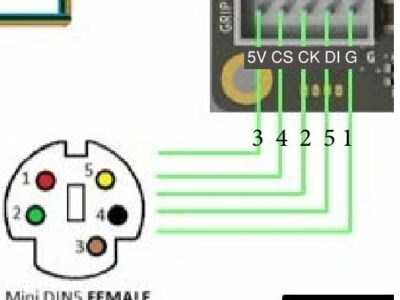
The wire colour on my 5pin JST connector followed the layout below, check that yours are the same before following this layout:
Pin – Colour on mini-DIN – Function from Table – Board Text – JST cable Colour
3 – Black – 5VDC – 5V – Brown
4 – Red – CS – CS – Black
2 – White – CK – CK – Green
5 – Yellow – D – DI – Yellow
1 – Orange – GND – G – Red
Note that the board text is offset from the pins on the picture so don’t line up the pin numbers on the diagram green lines. The diagram would be clearer if it was shown like the below:
- Below is shift register wiring to the VPC mainboard, if using a shift register.

I used a Thrustmaster Warthog joystick so this part was not applicable to my build
Step 1
Install Bearings into Pillow Blocks
- Insert two 6802 bearings into all four Core Joint Pillow Blocks. The bearing faces should be flush with the outer faces of the Pillow Block

Step 2
Mount Pillow Block/Bearing Assemblies onto Thrustmaster Stick Connector
- Slide one Pillow Block/Bearing Assembly onto each bearing post of the Thrustmaster Stick Connector
- SUPPORT THE BEARING POSTS ON THE STICK FROM THE INSIDE (GREEN ARROW) AS YOU SLIDE THE PILLOW BLOCKS ON TO PREVENT BREAKING THE STICK AT THE FORK.
- Secure with 19mm washers and M4x10 screws
- The Pillow Blocks should spin freely when secured
The M4x10 screws noted in this step should be M5x10 screws. The hole in the stick connector is M4 but is not threaded so the M5 is needed to install this screw. I did not install these screws or washers because my bearings were a good fit and did not need these to keep them in place. When the bearing is in place it cannot slide off the stick connector.

Step 3
Mount Pillow Block/Bearing Assemblies onto Core Joint
- Slide one Pillow Block/Bearing Assembly onto each bearing post of the Core Joint
- Secure with 19mm washers and M4x10 screws
- The Pillow Blocks should spin freely when secured
The M4x10 screws noted in this step should be M5x10 screws. The hole in the pillow block bearing assembly is M4 but is not threaded so the M5 is needed to install this screw. I did not install these screws or washers because my bearings were a good fit and did not need these to keep them in place. When the bearing is in place it cannot slide off the stick connector.

Step 4
Assemble Stick Connector/Core Joint
- Wire the 5pin mini din connector for the grip wiring to the JST connector for the mainboard.
- Be sure to extend the wires for enough reach to the mainboard.
- Extend the wires and solder them to the loose wires for the JST connector.
- Run the extended wires through the stick connector and out the front hole.
- Insert the wires into the connector in the proper locations in the JST connector based on the diagrams
- Mount TM Stick Connector to Core Joint as shown
- Insert M5x60 bolt into Core Joint
- Snug an M5 nut and washer down onto Core Joint
- Place an M5 washer on top of M5 nut
- Place TPU bumper on Core Joint around M5 Nut and Washers
- Snap F625ZZ bearing into base of Stick Connector
- Press Stick Connector onto Core Joint
- Drop second F625ZZ bearing into Stick Connector and press down as shown
- Place a dab of loctite into the M5 nut
- Place a dab of loctite into the M5 nut
- Drop M5 washer onto M5x60 Bolt and thread M5 Nut onto Bolt and make snug (no need to HULK it down)
- DO NOT USE A WASHER DIAMETER WHICH REACHES THE OUTER BEARING RACE EDGE AS THIS WILL LOCK UP THE JOINT. IT NEEDS TO BE ABLE TO ROTATE SLIGHTLY
This assembly was confusing for some parts.
- I did not assemble the electronic wires in this step, it can be done later in step 11 which is a better time to route the wiring in my opinion.
- Follow the steps per the guide bullet points, the lower core joint assembly is made first, then this is connected to the stick connector.
- The F625ZZ inner bearing is pushed through the top connection and moved with the M5x60 bolt in the correct orientation. The washer and nut is then dropped through the top opening and moved with the bolt to the correct orientation, screw it in lightly then I used a screwdriver wedged between the nut and the inside wall to stop the nut from rotating when turning the M5x60 bolt to snug the connection.
- Note that this connection needs to allow rotation of the core joint relative to the stick connection when gimbal is in use so the warnings about not overtightening are important.

Step 5
Prep Gimbal Frames
- Press a 6808 bearing on to each end of the Roll and Pitch Gimbal Frames
- The Gimbal face which mates to the pulleys should extend beyond the bearing face and the bearings should be fully seated against the frame
- Glue (6) M4 nuts into the Gimbal Frame recesses
- You only need to glue nuts into one side of the frame where the pulley will mount

Step 6
Mount The Roll Gimbal Frame to Pillow Block/Bearing Assemblies
- Push down and mount Roll Gimbal Frame to the Pillow Block/Bearing Assemblies
- Be sure to position the end of the Gimbal Frame with the nuts glued in from Step5, to the REAR (opposite of the hole in the Stick Adapter)
- Secure Pillow Blocks with (2) M5 bolts each

Step 7
Mount The Pitch Gimbal Frame to Pillow Block/Bearing Assemblies
- Be sure to position the end of the Gimbal Frame with the nuts glued in from Step5, to the RIGHT
- Push down and mount the Pitch Gimbal frame into Pillow Block/Bearing Assemblies
- Secure Pillow Blocks with (2) M5 bolts each
- Run the Grip Button Wire down through the center of the Gimbal Assembly

Step 8
Install Stick/Gimbal Assembly into Base Box
- Slide the Gimbal Group into the Rear, Mid, and Right Panel mounting holes

This is the first step when the bearing retainers are installed. I installed all of the bearing retainers (front and rear) but I had some creaking and a slight resistance to the movement of the gimbal so I removed all of the inner bearing retainers to allow some more flexibility of the bearing within the wall. My 3d printed walls are not perfectly straight due to the corners detaching from the print bed so I think the binding was due to this wall misalignment. The bearings are restrained on the outside in all 4 directions so the inner bearing retainers are not required in my opinion. This seemed to remove the gimbal resistance.
Step 9
Install Stick/Gimbal Assembly into Base Box (cont)
- Secure the Mid Panel with (2) M4x8 screws and the Mid, Right and Rear Gimbal Bearings Retainers using (4) M3x16 screws and M3 nuts each. Thereby locking the Gimbal Group into the Panels
- Secure the Right Panel to the Rear Panel with (3) M4x12 Screws
- Squeeze the outer retainer rings flush against the case panels while tightening
retainer screw
The M4x8 screws are to the right of the image into the mid panel and the M3x16 screws are the others in the image.


Step 10
Install Pitch and Roll Motors
- Mount the motors to Right and Rear Panel with (4) M6x16 screws each , snug but not tight (you will adjust position later)
- MOTORS ARE MAKRED “PITCH ID2” and “ROLL ID1” BE SURE TO MOUNT THEM PROPERLY, AS NEATNESS COUNTS.
- The Pitch motor mounts to the Right panel
- The Roll motor mounts to the Rear Panel
I mounted the motors with the electrical connections to the top of the pitch motor and to the side of the roll motor

Step 11
Install Left Panel and Mainboard
- Mount Left Panel to Mid Panel with (2) M4x8 screws and secure Gimbal Bearing with Retainer and (4) M3x16 screws and M3 nuts
- Mount the Left Panel to the Rear Panel with (3) M4-12 screws
- Glue Mainboard Mount into Gimbal Bearing Inner Retainer
- Mount Mainboard with (4) M3x4 screws
- Connect power wires from both Motors to the Mainboard
- Connect the data wire leads from both Motors to the Mainboard
- Route the Grip Wire between the Mid Panel and Pitch Motor to connect to the Mainboard

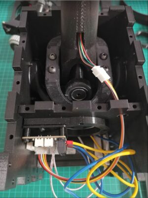
The cable length needed for the 5 pin JST is 200mm long. I added a 5 pin JST connector to the mini din connection (after it was installed), unfortunately the hole in the thrustmaster stick connector was not large enough for the JST connector to be installed before the wire is routed, so the wire needs to be installed and the connector installed after it if using the same approach. I ordered a female 5pin 200mm long cable to extend the cable to the main board and installed a male JST connector on the end of it to connect to the main board. The guide said to route the cable down between the pitch motor and the mid panel but it was clashing with the movement so I added a hole in the mid panel to pass the cable through it. I drilled the hole with a 10mm bit but it would be better to add an opening in the 3d printed panel for a better finish.
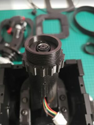
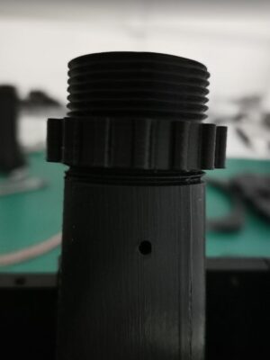
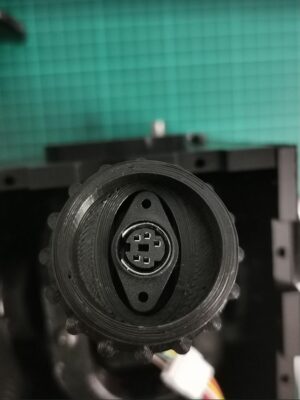
I re-modelled and 3d printed a different main board mount because the 3d printed mount did not align correctly. I also noticed that the mini-DIN connector I have did not fit into the 3d printed stick connector, it is also orientated rotated to the left for a centre stick positioning. I modelled and 3d printed a new screwed adapter with the geometry for my mini-DIN connector and used this instead of the default connector. The adapter tightened at the correct position to keep the orientation straight, but a retainer nut can be used to make adjustments if needed. These 3d print files are available here:
Step 12
Mount reset switch and potentiometers to Top Panel
The reset switch wiring is 200mm long JST connector and soldered to the switch.
The potentiometer wiring is 200mm long JST connector and soldered to the potentiometer.
Potentiometer wiring photo is shown below, these are soldered to the JST cables and connected to the mainboard.

Step 13
Mount fan and grill to Front Panel with (4) M3x30 screws and M3 nuts
The fan I got didn’t seem to fit well, nor did the screws so I assume I purchased a fan that was too thick. I will purchase another fan to install at a later date.

Step 14
Mount Top Panel
- Secure the Top Panel only with (10) M4x8 screws
- Connect E-Stop switch plug
- Make sure the wires to the potentiometers and E-Stop switch are tucked as close to the Mid Panel as possible to be clear of fan when installed

Step 15
Install USB and Power plugs
- Press the Power Socket into the retainer plate
- Insert the Plug and Plate into the Rear Plate
- Secure with (2) M3x16 screws and M3 washers and nuts
- Snap the USB plug into the outer retainer plate and insert into the Rear Plate
- Slide the inner retainer over the USB plug
- Secure with (2) M3x16 screws and M3 washers and nuts
- Connect the positive connection for the Power Socket to one leg of the E-Stop Switch
- Plug the JST connector end of the USB Socket into the Mainboard
The retainers for the power supply cable did not fit for me, so the power chord is protruding from the box for now.
The USB retainer is very fragile, I snapped mine when installing so printed another one to install, this was a good fit into the side of the box.

Step 16
Install Front Panel
- Plug the JST connector for the Fan into the Mainboard
- Mount Front Panel to the Top and Side Panels.
- Only secure with M4x12 screws on the Left and Right Panels. The screws for the Top Cover will fill the top two holes and the remaining top plate hole

Step 17
Install bottom panel
- Secure Bottom Panel with (12) M4x8 screws

Step 18
Install Pitch and Roll Pulleys
- Mount pitch and roll Gimbal 74T pulley to gimbals with (6) M4x35 screws each
- Use one or two washers on the screw head to keep screw end from contacting the Gimbal on the inside
- Install the motor drive pulley on the motor shaft
- Align the pulley so the outer lip of the drive pulley is in line with the outer lip of the Gimbal Pulley
- Use blue Loctite on the drive pulley grub screws and secure it to the flat of the motor shaft

Step 19
Boot Install
- Glue E-Stop guard into slot on top panel
- Mount Top Panel Cover corner guard to Top Panel with (4) M4x12 Socket Head screws


Step 20
Centering
- Slide the Centering Tool over the stick connector as show

Belts install and Motor Centering
Congratulations, you made it this far!
Now it is time to connect the stick base to power and your PC USB port.
- Install and open the latest VPForce FFB Configurator.
- With the Emergency Stop Switch Depressed, plug the 24V power into the base.
- Plug in the USB connector to the base, the base should beep and be detected by the PC.
- Twist the Emergency Stop Switch to unlock it and energize the motors.
- Loosen the PITCH (side) motor mount bolts and slide the Motor as close to the Gimbal Pulley as possible.
- Make sure the Centering Tool is pressed firmly against the Top Panel.
- Slide the Pitch Belt over the pulleys. Motor pulley first, then Gimbal Pulley.
- Slide the Motor away from the Gimbal Pulley to tension the belt as much as you can by hand and tighten the Motor mount bolts. Tighten the bolts furthest from the Gimbal Pulley first, and then those closer. This will add a little more tension to the belt as you tighten.
- Repeat the process for the Roll pulleys.
- Once all the motor mount bolts are tight, in the VPC software:
- Click “Auto Calibrate”
- In the FFB Axes Setup section
- Set the X:min and Y:min to 0
- Set X:max and Y:max to 4096
- Click on “Auto Calibrate”, “Apply Settings” and then “Store Settings”
- Raw X and Y Values in the left panel should be very close to 2000
- Remove the Centering Tool
- Move on to install the Limiter and boot before final axes calibration
- Final Axes calibration is outlined in the VPForce Manual <LINK HERE>
The main points to note in this step is to place the centering tool on the stick and remove or loosen the belts if they are already installed. Rotate the motors so that the value of x:min and y:min are close to 2000 and re-fit the belts keeping it as close to 2000 as possible. I don’t know how close to 2000 it needs to be but mine were XXXX and XXXX.
Then click the following:
- Auto-Calibrate
- Set X:min = 0 and X:max to 4096
- Set Ymin=0 and Ymax to 4096
- Auto-Calibrate
- Apply Settings
- Store Settings
Move onto the next steps to install the boot and end-stop limits before coming back to the configurator.

Step 21
Boot Install (Cont)
- Place Throw Limiters into the opening in the Top Panel

Step 22
Boot Install (Cont)
- Stitch together 4 panels of the textile of your choice based on the template measurements
- Be sure to sew the panels together inside out

Step 23
Boot Clamp Install (Cont)
- Place lower boot clamp on top panel
- Turn boot inside out
- Slide top of boot over stick connector and between Collar and ck
- Punch holes into boot to secure with boot ring and (4) M3x16 screws
- Fold boot down and hot glue to lower boot clamp leaving enough slack for full stick deflection
- Punch holes in boot for clamp mount screws
- Trim excess boot material from outside of lower clamp

Step 23
Boot Clamp Install (Cont)
- Place upper boot clamp on top panel and secure with (4) M4x35 bolts

Step 24
The guide refers to the manual for axis calibration in step 20. We will adjust the in game settings now
